Nissan Rogue Service Manual: Wiring diagram
CAN SYSTEM
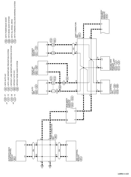
Wiring Diagram - CAN SYSTEM -
 System description
COMPONENT PARTS
Component Parts Location
Air bag diagnosis sensor unit
AV control unit
Around view monitor control unit
Chassis control module
ABS actuator and electric unit (contr ...
 Basic inspection
DIAGNOSIS AND REPAIR WORKFLOW
Interview Sheet
...
Other materials:
On board diagnostic (OBD) system
Diagnosis Description
This system is an on board diagnostic system that records exhaust
emission-related diagnostic information
and detects a sensors/actuator-related malfunction. A malfunction is indicated
by the malfunction indicator
lamp (MIL) and stored in control module memory as a DTC. ...
Preparation
Special Service Tools
The actual shape of the tools may differ from those illustrated here.
Tool number
(TechMate No.)
Tool name
Description
—
(165-GR8-1200KIT-NI)
Multitasking battery and electrical diagnostic
station
Testing batteries, starting and ...
Warning/indicator lights and audible reminders
Anti-lock Braking System (ABS)
warning light
Brake warning light
Charge warning light
Low tire pressure warning light
Low windshield washer fluid warning light (if so
equipped)
Master warning light
Power s ...
