Nissan Rogue Service Manual: P0101 MAF sensor
DTC Description
DTC DETECTION LOGIC
| DTC No. | CONSULT screen terms (Trouble diagnosis content) | DTC detecting condition |
| P0101 | MAF SEN/CIRCUIT-B1 (Mass or volume air Flow ″A″ circuit range/ performance) |
|
POSSIBLE CAUSE
- Harness or connectors (MAF sensor circuit is open or shorted.)
- Intake air leaks
- MAF sensor
- EVAP control system pressure sensor
- Intake air temperature sensor
- Sensor power supply 2 circuit
FAIL-SAFE
- Traveling control mode (Accelerator angle variation control)
- Traveling control mode (Engine output control)
- Device fix mode
DTC CONFIRMATION PROCEDURE
1.CHECK DTC PRIORITY
If DTC P0101 is displayed with other DTC, first perform the trouble diagnosis for other DTC.
Is applicable DTC detected? YES >> Perform diagnosis of applicable. Refer to EC-93, "DTC Index".
NO >> GO TO 2.
2.PRECONDITIONING
If DTC CONFIRMATION PROCEDURE has been previously conducted, always perform the following procedure before conducting the next test.
- Turn ignition switch OFF and wait at least 10 seconds.
- Turn ignition switch ON.
- Turn ignition switch OFF and wait at least 10 seconds.
>> GO TO 3.
3.PERFORM DTC CONFIRMATION PROCEDURE
- Start engine and warm it up to normal operating temperature.
- Drive the vehicle for at least 5 seconds under the following conditions:
CAUTION: Always drive vehicle at safe speed.
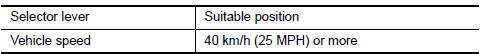
NOTE:
- The gear must be fixed while driving the vehicle.
- Keep the accelerator pedal as steady as possible during cruising.
- Check 1st trip DTC.
Is 1st trip DTC detected? YES >> Proceed to EC-199, "Diagnosis Procedure".
NO >> INSPECTION END
Diagnosis Procedure
1.CHECK DTC PRIORITY
If DTC P0101 is displayed with other DTC, first perform the trouble diagnosis for other DTC.
Is applicable DTC detected? YES >> Perform diagnosis of applicable. Refer to EC-93, "DTC Index".
NO >> GO TO 2.
2.CHECK INTAKE SYSTEM
Check the following for connection.
- Air duct
- Vacuum hoses
- Intake air passage between air duct and intake manifold
Is the inspection result normal? YES >> GO TO 3.
NO >> Reconnect the parts.
3.CHECK MASS AIR FLOW (MAF) SENSOR POWER SUPPLY
- Turn ignition switch OFF.
- Disconnect MAF sensor harness connector.
- Turn ignition switch ON.
- Check the voltage between MAF sensor harness connector and ground.
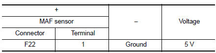
Is the inspection result normal? YES >> GO TO 5.
NO >> GO TO 4.
4.CHECK SENSOR POWER SUPPLY 2 CIRCUIT
Perform EC-484, "Diagnosis Procedure".
Is the inspection result normal? YES >> Perform the trouble diagnosis for power supply circuit.
NO >> Repair or replace error-detected parts.
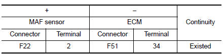
5.CHECK MAF SENSOR GROUND CIRCUIT
- Turn ignition switch OFF.
- Disconnect ECM harness connector.
- Check the continuity between MAF sensor harness connector and ECM harness connector.
- Also check harness for short to power.
Is the inspection result normal? YES >> GO TO 6.
NO >> Repair or replace error-detected parts.
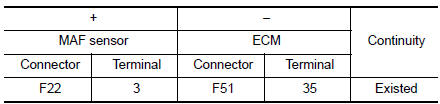
6.CHECK MAF SENSOR INPUT SIGNAL CIRCUIT
- Check the continuity between MAF sensor harness connector and ECM harness connector.
- Also check harness for short to ground and to power.
Is the inspection result normal? YES >> GO TO 7.
NO >> Repair or replace error-detected parts
7.CHECK INTAKE AIR TEMPERATURE SENSOR
Check the intake air temperature sensor. Refer to EC-207, "Component Inspection".
Is the inspection result normal? YES >> GO TO 8.
NO >> Replace MAF sensor (with intake air temperature sensor). Refer to EM-24, "Exploded View".
8.CHECK EVAP CONTROL SYSTEM PRESSURE SENSOR
Check the EVAP control system pressure sensor. Refer to EC-330, "Component Inspection".
Is the inspection result normal? YES >> GO TO 9.
NO >> Replace EVAP control system pressure sensor. Refer to FL-22, "Removal and Installation".
9.CHECK MAF SENSOR
Check the MAF sensor. Refer to EC-200, "Component Inspection".
Is the inspection result normal? YES >> GO TO 10.
NO >> Replace MAF sensor. Refer to EM-24, "Exploded View".
10.CHECK INTERMITTENT INCIDENT
Refer to GI-41, "Intermittent Incident".
>> INSPECTION END
Component Inspection
1.CHECK MASS AIR FLOW SENSOR-1
 With CONSULT
- Turn ignition switch OFF.
- Reconnect all harness connectors disconnected.
- Start engine and warm it up to normal operating temperature.
- Connect CONSULT and select “DATA MONITOR” mode of “ENGINE”.
- Select “MASS AIR FLOW SENSOR (Hz)” and check indication.
*: Check for linear frequency rise in response to engine being increased to about 4,000 rpm.
Is the inspection result normal? YES >> INSPECTION END
NO >> GO TO 2.
2.CHECK FOR THE CAUSE OF UNEVEN AIR FLOW THROUGH MASS AIR FLOW SENSOR
- Turn ignition switch OFF.
- Check for the cause of uneven air flow through mass air flow sensor. Refer to the following.
- Crushed air ducts
- Malfunctioning seal of air cleaner element
- Uneven dirt of air cleaner element
- Intake valve deposits
- Improper specification of intake air system parts
Is the inspection result normal? YES >> GO TO 4.
NO >> GO TO 3.
3.CHECK MASS AIR FLOW SENSOR-2
 With CONSULT
- Repair or replace malfunctioning part.
- Start engine and warm it up to normal operating temperature.
- Connect CONSULT and select “DATA MONITOR” mode of “ENGINE”.
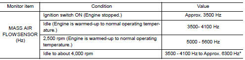
- Select “MASS AIR FLOW SENSOR (Hz)” and check indication.
| Monitor item | Condition | Value |
| MASS AIR FLOW SENSOR (Hz) | Ignition switch ON (Engine stopped.) | Approx. 3500 Hz |
| Idle (Engine is warmed-up to normal operating temperature.) | 3500- 4100 Hz | |
| 2,500 rpm (Engine is warmed-up to normal operating temperature.) | 5000 - 5600 Hz | |
| Idle to about 4,000 rpm | 3500 - 4100 Hz to Approx. 6300 Hz* |
*: Check for linear frequency rise in response to engine being increased to about 4,000 rpm.
Is the inspection result normal? YES >> INSPECTION END
NO >> GO TO 4.
4.CHECK MASS AIR FLOW SENSOR-3
With CONSULT
- Turn ignition switch OFF.
- Disconnect mass air flow sensor harness connector and reconnect it again.
- Start engine and warm it up to normal operating temperature.
- Connect CONSULT and select “DATA MONITOR” mode of “ENGINE”.
- Select “MASS AIR FLOW SENSOR (Hz)” and check indication.
| Monitor item | Condition | Value |
| MASS AIR FLOW SENSOR (Hz) | Ignition switch ON (Engine stopped.) | Approx. 3500 Hz |
| Idle (Engine is warmed-up to normal operating temperature.) | 3500- 4100 Hz | |
| 2,500 rpm (Engine is warmed-up to normal operating temperature.) | 5000 - 5600 Hz | |
| Idle to about 4,000 rpm | 3500 - 4100 Hz to Approx. 6300 Hz* |
*: Check for linear frequency rise in response to engine being increased to about 4,000 rpm.
Is the inspection result normal? YES >> INSPECTION END
NO >> Clean or replace mass air flow sensor. Refer to EM-24, "Exploded View".
 P0078 EVT control solenoid valve
DTC Description
DTC DETECTION LOGIC
DTC No.
CONSULT screen terms
(Trouble diagnosis content)
DTC detecting condit
P0078
EX V/T ACT/CIRC-B1
(Exhaust valve control solen ...
 P0102, P0103 MAF sensor
DTC Description
DTC DETECTION LOGIC
DTC No.
CONSULT screen terms
(Trouble diagnosis content)
DTC detecting condition
P0102
MAF SEN/CIRCUIT-B1
(Mass or volume air flow ...
Other materials:
Precaution
Precaution for Supplemental Restraint System (SRS) "AIR BAG" and "SEAT
BELT
PRE-TENSIONER"
The Supplemental Restraint System such as “AIR BAG” and “SEAT BELT PRE-TENSIONER”,
used along
with a front seat belt, helps to reduce the risk or severity of injury to the
...
Precaution
Precaution for Supplemental Restraint System (SRS) "AIR BAG" and "SEAT
BELT
PRE-TENSIONER"
The Supplemental Restraint System such as “AIR BAG” and “SEAT BELT PRE-TENSIONER”,
used along
with a front seat belt, helps to reduce the risk or severity of injury to the
...
C1120, C1122, C1124, C1126 ABS in valve system
DTC Logic
DTC DETECTION LOGIC
DTC
Display Item
Malfunction detected condition
Possible causes
C1120
FR LH IN ABS SOL
When a malfunction is detected in front LH ABS IN
valve.
Harness or connector
ABS actuator and electric unit
(control uni ...
