Nissan Rogue Service Manual: Interior room lamp control circuit
Description
Controls each interior room lamp (ground side) by PWM signal.
NOTE: PWM signal control period is approximately 250 Hz (in the gradual brightening/dimming).
Component Function Check
CAUTION: Before performing the diagnosis, check that the following is normal.
- Interior room lamp power supply
- Map lamp bulb
- Room lamp bulb
1.CHECK INTERIOR ROOM LAMP CONTROL FUNCTION
 CONSULT ACTIVE TEST
- Switch the map lamp switch and room lamp switch to DOOR.
- Turn power switch ON.
- Select ŌĆ£INT LAMPŌĆØ of ŌĆ£BCMŌĆØ active test item.
- With operating the test items, check that each interior room lamp turns ON/OFF (gradual brightening/dimming).
On : Interior room lamp gradual brightening
Off : Interior room lamp gradual dimming
Does the interior room lamp turns ON/OFF (gradual brightening/dimming)? YES >> Interior room lamp control circuit is normal.
NO >> Refer to INL-49, "Diagnosis Procedure".
Diagnosis Procedure
1.CHECK INTERIOR ROOM LAMP CONTROL OUTPUT
CONSULT ACTIVE TEST
- Turn power switch OFF.
- Remove all the bulbs of map lamp and room lamp.
- Turn power switch ON.
- Select ŌĆ£INT LAMPŌĆØ of ŌĆ£BCMŌĆØ active test item.
- With operating the test item, check continuity between BCM harness connector and ground.
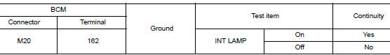
Is the inspection result normal? YES >> GO TO 2.
Fixed ON>>GO TO 3.
Fixed OFF>>Replace BCM. Refer to BCS-75, "Removal and Installation" (with Intelligent Key system) or BCS-135, "Removal and Installation" (without Intelligent Key system).
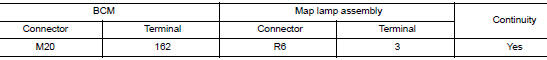
2.CHECK INTERIOR ROOM LAMP CONTROL OPEN CIRCUIT
- Turn power switch OFF.
- Disconnect BCM connector, map lamp assembly and room lamp connector.
- Check continuity between BCM harness connector and map lamp harness connector.
- Check continuity between BCM harness connector and room lamp harness connector.
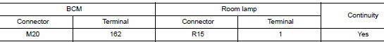
Is the inspection result normal? YES >> Replace map lamp or room lamp.
NO >> Repair or replace harnesses.
3.CHECK INTERIOR ROOM LAMP CONTROL SHORT CIRCUIT
- Turn power switch OFF.
- Disconnect BCM connector, map lamp connector and room lamp connector.
- Check continuity between BCM harness connector and ground.
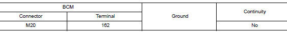
Is the inspection result normal? YES >> Replace BCM. Refer to BCS-75, "Removal and Installation" (with Intelligent Key system) or BCS- 135, "Removal and Installation" (without Intelligent Key system).
NO >> Repair or replace harnesses.
 Interior room lamp power supply circuit
Description
Provides the interior room lamp power supply. Also cuts the power supply when
the interior room lamp battery
saver is activating.
Component Function Check
1.CHECK INTERIOR ROOM LAMP ...
 Luggage room lamp circuit
Description
Controls the luggage room lamp (ground side) to turn the luggage room lamp ON
and OFF.
Diagnosis Procedure
CAUTION:
Before performing the diagnosis, check that the following is norma ...
Other materials:
USB (Universal Serial Bus) Connection Port (models without Navigation
System)
(if so equipped)
USB (Universal Serial Bus) Connection Port (models without Navigation System)
Connecting a device to the USB
Connection Port
WARNINGDo not connect, disconnect, or operate the
USB device while driving. Doing so can be
a distraction. If distracted you could lose
control of your ...
P1217 engine over temperature
DTC Description
DTC DETECTION LOGIC
If the cooling fan or another component in the cooling system malfunctions,
engine coolant temperature will
rise.
When the engine coolant temperature reaches an abnormally high temperature
condition, a malfunction is
indicated.
DTC No.
CONSUL ...
Removal and installation
FRONT WHEEL HUB
Exploded View
Wheel hub and bearing
Cotter pin
Nut retainer
Wheel hub lock nut
Hub bolt
Splash guard
Steering knuckle
Removal and Installation
REMOVAL
Remove front wheel and tire using power tool. Refer to WT-57,
" ...
