Nissan Rogue Service Manual: Luggage room lamp circuit
Description
Controls the luggage room lamp (ground side) to turn the luggage room lamp ON and OFF.
Diagnosis Procedure
CAUTION: Before performing the diagnosis, check that the following is normal.
- Interior room lamp power supply
- Luggage room lamp bulb
1.CHECK LUGGAGE ROOM LAMP OUTPUT
- Turn power switch OFF.
- Remove the luggage room lamp bulb.
- Check continuity between BCM harness connector and ground.
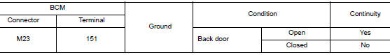
Is the inspection result normal? YES >> GO TO 2.
Fixed ON>>GO TO 3.
Fixed OFF>>Replace BCM. Refer to BCS-75, "Removal and Installation" (with Intelligent Key system) or BCS-135, "Removal and Installation" (without Intelligent Key system).
2.CHECK LUGGAGE ROOM LAMP OPEN CIRCUIT
- Disconnect BCM connector.
- Check continuity between BCM harness connector and luggage room lamp harness connector.
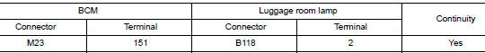
Is the inspection result normal? YES >> Replace luggage room lamp.
NO >> Repair or replace harnesses.
3.CHECK LUGGAGE ROOM LAMP SHORT CIRCUIT
- Disconnect BCM connector.
- Check continuity between BCM harness connector and ground.
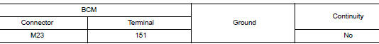
Is the inspection result normal? YES >> Replace BCM. Refer to BCS-75, "Removal and Installation" (with Intelligent Key system) or BCS- 135, "Removal and Installation" (without Intelligent Key system).
NO >> Repair or replace harnesses.
 Interior room lamp control circuit
Description
Controls each interior room lamp (ground side) by PWM signal.
NOTE:
PWM signal control period is approximately 250 Hz (in the gradual
brightening/dimming).
Component Function Check
...
 Power switch illumination circuit
Description
Provides the power supply and the ground to control the power switch
illumination.
Component Function Check
1.CHECK POWER SWITCH ILLUMINATION OPERATION
CONSULT ACTIVE TEST
...
Other materials:
Wiring diagram
CHASSIS CONTROL
Wiring Diagram
...
ECU diagnosis information
ABS ACTUATOR AND ELECTRIC UNIT (CONTROL UNIT)
Reference Value
CONSULT DATA MONITOR STANDARD VALUE
NOTE:
The following table includes information (items) inapplicable to this vehicle.
For information (items) applicable
to this vehicle, refer to CONSULT display items.
Note 1: Confi ...
The liftgate open warning continues displaying, or does
not display
Description
The liftgate open warning is displayed continuously even though the
liftgate is closed.
The liftgate open warning is not displayed even though the
liftgate is open.
Diagnosis Procedure
1.CHECK BCM INPUT SIGNAL
Check the BCM input signal. Refer to DLK-149, "Com ...
