Nissan Rogue Service Manual: ECU diagnosis information
ABS ACTUATOR AND ELECTRIC UNIT (CONTROL UNIT)
Reference Value
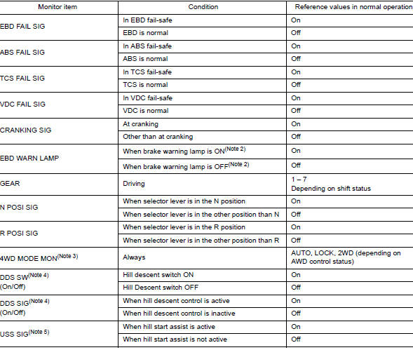
CONSULT DATA MONITOR STANDARD VALUE
NOTE: The following table includes information (items) inapplicable to this vehicle. For information (items) applicable to this vehicle, refer to CONSULT display items.
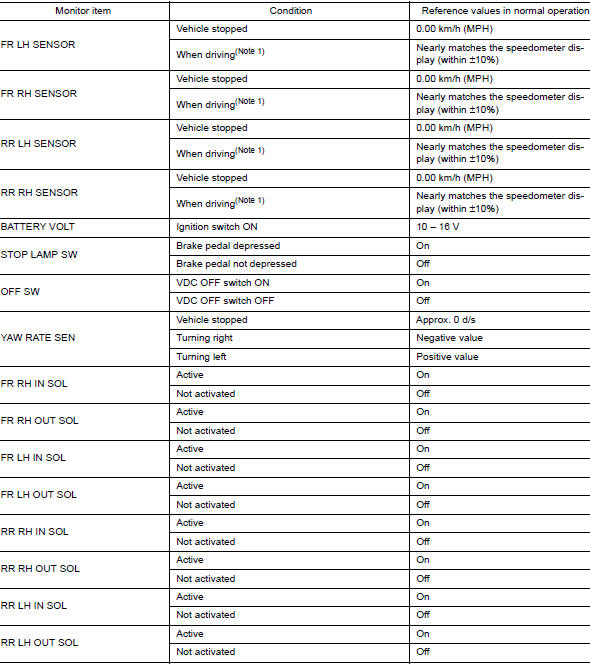
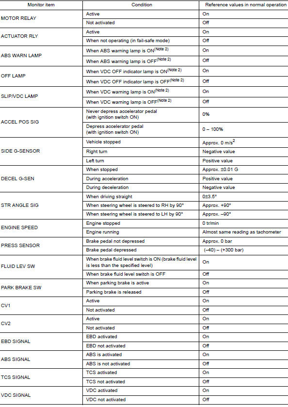
Note 1: Confirm tire pressure is standard value.
Note 2: Refer to BRC-14, "System Description" for ON/OFF conditions of each
warning lamp and indicator
lamp.
Note 3: AWD models
Note 4: DDS (Downhill Drive Support)
Note 5: USS (Hill Start Assist)
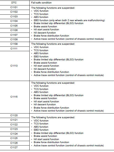
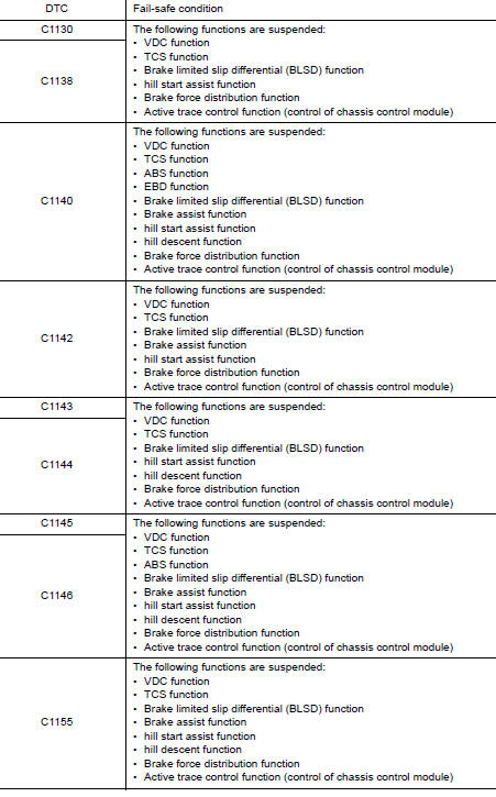
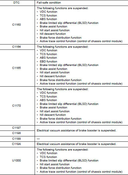
Fail-Safe
VDC FUNCTION, TCS FUNCTION, BRAKE LIMITED SLIP DIFFERENTIAL FUNCTION, BRAKE ASSIST FUNCTION, hill start assist FUNCTION AND BRAKE FORCE DISTRIBUTION FUNCTION
VDC warning lamp in combination meter turn ON when a malfunction occurs in system [ABS actuator and electric unit (control unit)]. The control is suspended for VDC function, TCS function, Brake limited slip differential (BLSD) function, Brake assist function, hill start assist function and Brake force distribution function. The vehicle status becomes the same as models without VDC function, TCS function, Brake limited slip differential (BLSD) function, Brake assist function, hill start assist function and Brake force distribution function. However, ABS function and EBD function are operated normally.
ABS FUNCTION
ABS warning lamp and VDC warning lamp in combination meter turn ON when a malfunction occurs in system [ABS actuator and electric unit (control unit)]. The control is suspended for VDC function, TCS function, ABS function, Brake limited slip differential (BLSD) function, Brake assist function, hill start assist function and Brake force distribution function. The vehicle status becomes the same as models without VDC function, TCS function, ABS function, Brake limited slip differential (BLSD) function, Brake assist function, hill start assist function and Brake force distribution function. However, EBD function is operated normally.
NOTE: ABS self-diagnosis sound may be heard the same as in the normal condition, because self-diagnosis is performed when ignition switch turns ON and when vehicle initially starts.
EBD FUNCTION
ABS warning lamp, brake warning lamp and VDC warning lamp in combination meter turn ON when a malfunction occurs in system [ABS actuator and electric unit (control unit)]. The control is suspended for VDC function, TCS function, ABS function, EBD function, Brake limited slip differential (BLSD) function, Brake assist function, hill start assist function and Brake force distribution function. The vehicle status becomes the same as models without VDC function, TCS function, ABS function, EBD function, Brake limited slip differential (BLSD) function, Brake assist function, hill start assist function and Brake force distribution function.
DTC Inspection Priority Chart
When multiple DTCs are displayed simultaneously, check one by one depending on the following priority list.
|
Priority |
Detected item (DTC) |
| 1 |
|
| 2 |
|
| 3 |
|
| 4 |
|
| 5 |
|
| 6 |
|
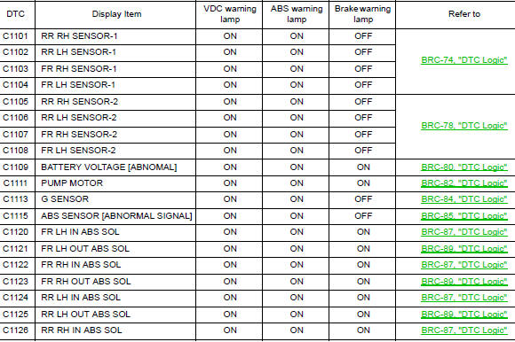
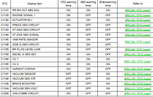
DTC Index
 Diagnosis system [ABS actuator and electric unit (control
unit)]
Diagnosis system [ABS actuator and electric unit (control
unit)]
CONSULT Function
APPLICATION ITEMS
CONSULT can display each diagnostic item using the diagnostic test modes as
follows.
Mode
Function description
ECU identification
...
 Wiring diagram
BRAKE CONTROL SYSTEM
Wiring Diagram
...
Other materials:
Side air spoiler
Exploded View
Side air spoiler
Clip
Removal and Installation
REMOVAL
Remove side air spoiler bolts (A).
1: Side air spoiler
B: Clips
Release clips using suitable tool (A) and remove side air spoiler
(1).
: Clips
INSTALLATION
Installation is in the rev ...
P1078 EVT control position sensor
DTC Description
DTC DETECTION LOGIC
DTC No.
CONSULT screen terms
(Trouble diagnosis content)
DTC detecting condition
P1078
EXH TIM SEN/CIRC-B1
(EXH TIM SEN/CIRC-B1)
An excessively high or low voltage from the sensor is sent to ECM.
POSSIBLE CAUSE
H ...
Wiring diagram
NAVIGATION WITH BOSE
Wiring Diagram
...
