Nissan Rogue Service Manual: Diagnosis system [ABS actuator and electric unit (control unit)]
CONSULT Function
APPLICATION ITEMS
CONSULT can display each diagnostic item using the diagnostic test modes as follows.
|
Mode |
Function description |
| ECU identification | Parts number of ABS actuator and electric unit (control unit) can be read. |
| Self Diagnostic Result | Self-diagnostic results and freeze frame data can be read and erased quickly.* |
| DATA MONITOR | Input/Output data in the ABS actuator and electric unit (control unit) can be read. |
| ACTIVE TEST | Input/Output data in the ABS actuator and electric unit (control unit) can be read. |
| WORK SUPPORT | Components can be quickly and accurately adjusted. |
| Re/programming, Configuration |
|
*: The following diagnosis information is erased by erasing.
- DTC
- Freeze frame data (FFD)
ECU IDENTIFICATION
ABS actuator and electric unit (control unit) part number can be read.
SELF DIAGNOSTIC RESULT
Refer to BRC-55, "DTC Index".
When ŌĆ£CRNTŌĆØ is displayed on self-diagnosis result,
- The system is presently malfunctioning.
When ŌĆ£PASTŌĆØ is displayed on self-diagnosis result,
- System malfunction in the past is detected, but the system is presently normal.
Freeze frame data (FFD)
The following vehicle status is recorded when DTC is detected and is displayed on CONSULT.
|
Item name |
Display item |
| IGN counter (0 ŌłÆ 39) | The number of times that ignition switch is turned ON after the DTC
is detected is displayed.
NOTE: Each time when ignition switch is turned OFF to ON, numerical number increases in 1 ŌåÆ 2 ŌåÆ 3...38 ŌåÆ 39. When the operation number of times exceeds 39, the number do not increase and ŌĆ£39ŌĆØ is displayed until self-diagnosis is erased. |
ACTIVE TEST
The active test is used to determine and identify details of a malfunction, based on self-diagnosis test results and data obtained in the DATA MONITOR. In response to instructions from CONSULT, instead of those from ABS actuator and electric unit (control unit) on the vehicle, a drive signal is sent to the actuator to check its operation.
CAUTION:
- Never perform ACTIVE TEST while driving the vehicle.
- Always bleed air from brake system before active test.
- Never perform active test when system is malfunctioning.
NOTE:
- When active test is performed while depressing the pedal, the pedal depressing stroke may change. This is not a malfunction.
- ŌĆ£TEST IS STOPPEDŌĆØ is displayed approx. 10 seconds after operation start.
- When performing active test again after ŌĆ£TEST IS STOPPEDŌĆØ is displayed, select ŌĆ£BACKŌĆØ.
- ABS warning lamp, brake warning lamp and VDC warning lamp may turn ON during active test. This is not a malfunction.
ABS IN Valve and ABS OUT Valve
When ŌĆ£UpŌĆØ, ŌĆ£KeepŌĆØ or ŌĆ£DownŌĆØ is selected on display screen, the following items are displayed when system is normal.
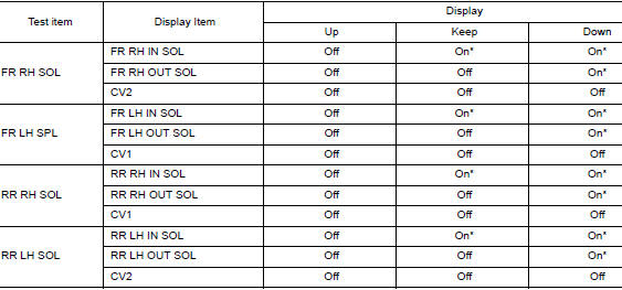
*: Immediately after being selected, status is ŌĆ£OnŌĆØ. Status changes to ŌĆ£OffŌĆØ after approx. 2 seconds.
ABS IN Valve (ACT) and ABS OUT Valve (ACT)
When ŌĆ£UpŌĆØ, ŌĆ£ACT UPŌĆØ or ŌĆ£ACT KEEPŌĆØ is selected on display screen, the following items are displayed when system is normal.
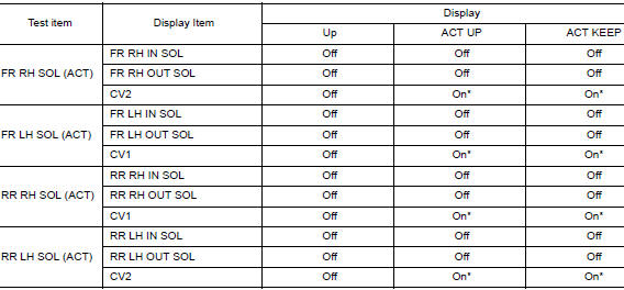
*: Immediately after being selected, status is ŌĆ£OnŌĆØ. Status changes to ŌĆ£OffŌĆØ after approx. 10 seconds.
ABS MOTOR
When ŌĆ£OnŌĆØ or ŌĆ£OffŌĆØ is selected on display screen, the following items are displayed when system is normal.
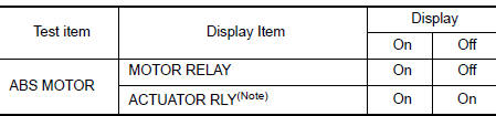
NOTE: Display occasionally changes On/Off for a moment after ignition switch is turned ON. This is operation for checking purposes and is not a malfunction.
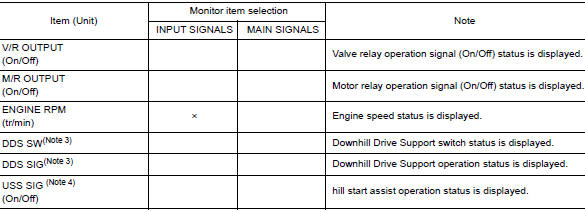
DATA MONITOR
NOTE: The following table includes information (items) inapplicable to this vehicle. For information (items) applicable to this vehicle, refer to CONSULT display items.
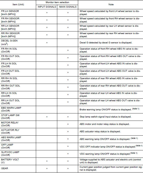
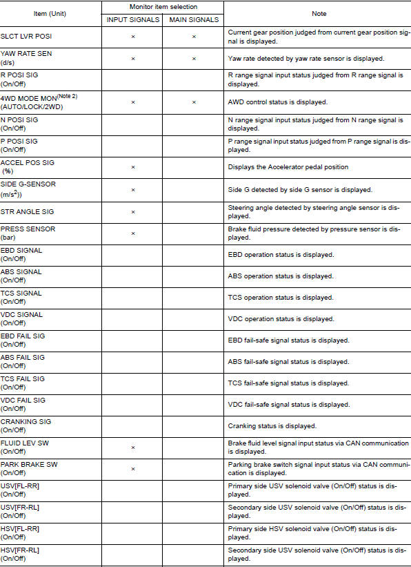
Note 1: Refer to BRC-14, "System Description" for ON/OFF conditions of each
warning lamp and indicator
lamp.
Note 2: AWD models
Note 3: DDSŌĆØ (Downhill Drive Support)
Note 4: USS (Hill Start Assist)
WORK SUPPORT
|
Conditions |
Description |
| ST ANGLE SENSOR ADJUSTMENT | Perform neutral position adjustment of steering angle sensor |
| DECEL G SEN CALIBRATION | Perform decel G sensor calibration. |
 System
System Description
The system switches fluid pressure of each brake caliper to increase, to
hold or to decrease according to
signals from control unit in ABS actuator and electric unit (contr ...
 ECU diagnosis information
ABS ACTUATOR AND ELECTRIC UNIT (CONTROL UNIT)
Reference Value
CONSULT DATA MONITOR STANDARD VALUE
NOTE:
The following table includes information (items) inapplicable to this vehicle.
For informa ...
Other materials:
ABC warning lamp
Component Function Check
1.CHECK ABS WARNING LAMP FUNCTION
Check that ABS warning lamp in combination meter turns ON for 1 second after
ignition switch is turned ON.
CAUTION:
Never start the engine.
Is the inspection result normal?
YES >> Inspection End.
NO >> Proceed to BRC-1 ...
Retained power operation does not operate properly
Diagnosis Procedure
1.CHECK FRONT DOOR SWITCH
Check (LH and RH) front door switches.
Refer to DLK-24, "Front Door Switch".
Is the inspection result normal?
YES >> GO TO 2.
NO >> Repair or replace the malfunctioning parts.
2.CONFIRM THE OPERATION
Confirm the operat ...
Front wiper arm
Exploded View
Front wiper blade (RH)
Front wiper arm (RH)
Front wiper arm cover
Front wiper drive assembly
Front wiper arm (LH)
Front wiper blade (LH)
Removal and Installation
REMOVAL
Move front wiper into the service position by turning the ignit ...
