Nissan Rogue Service Manual: System
System Description
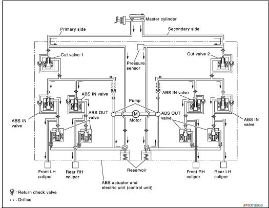
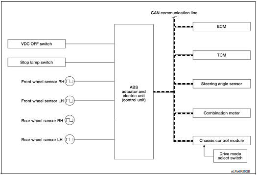
- The system switches fluid pressure of each brake caliper to increase, to hold or to decrease according to signals from control unit in ABS actuator and electric unit (control unit). This control system is applied to VDC function, TCS function, ABS function, EBD function, brake limited slip differential (BLSD) function, brake assist function, hill start assist function and Brake force distribution function.
- Fail-safe function is available for each function and is activated by each function when system malfunction occurs.
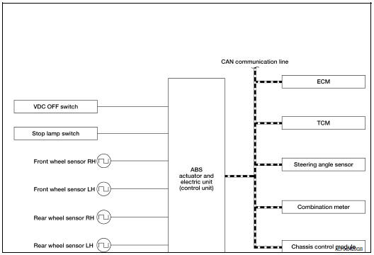
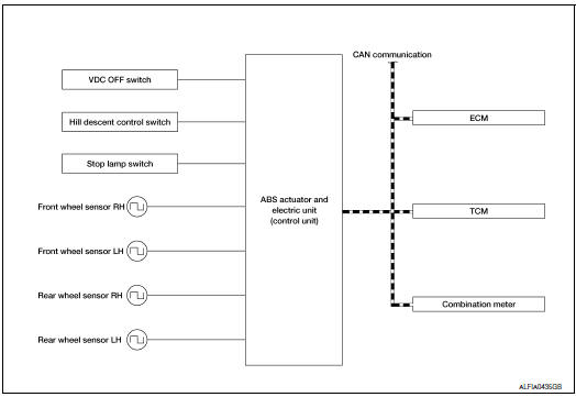
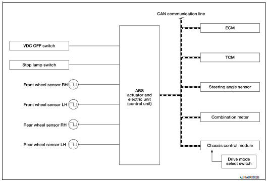
SYSTEM DIAGRAM
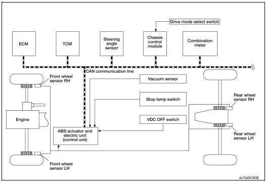
INPUT SIGNAL AND OUTPUT SIGNAL
Major signal transmission between each unit via communication lines is shown in the following table.
|
Component |
Signal description |
| ECM | Mainly transmits the following signals to ABS actuator and electric
unit (control unit) via CAN
communication.
Mainly receives the following signals from ABS actuator and electric unit (control unit) via CAN communication.
|
| TCM | Mainly transmits the following signals to ABS actuator and electric
unit (control unit) via CAN
communication.
|
| Chassis control module | Mainly transmits the following signals to ABS actuator and electric
unit (control unit) via CAN
communication.
|
| Combination meter | Mainly receives the following signals from ABS actuator and electric
unit (control unit) via CAN
communication.
Mainly receives the following signals from ABS actuator and electric unit (control unit) via CAN communication.
|
| Steering angle sensor | Mainly transmits the following signals to ABS actuator and electric
unit (control unit) via CAN
communication.
|
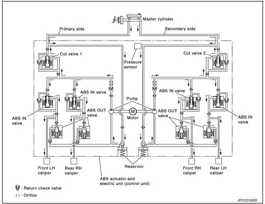
VALVE OPERATION (ABS AND EBD)
Each valve is operated and fluid pressure of brake caliper is controlled.
When ordinary brake is applied and ABS is in operation (when pressure increases).
|
Name |
Not activated |
When Pressure Increases |
| Cut valve 1 | Power supply is not supplied (open) | Power supply is not supplied (open) |
| Cut valve 2 | Power supply is not supplied (open) | Power supply is not supplied (open) |
| ABS IN valve | Power supply is not supplied (open) | Power supply is not supplied (open) |
| ABS OUT valve | Power supply is not supplied (close) | Power supply is not supplied (close) |
| Each caliper (fluid pressure) |
— |
Pressure increases |
When front RH wheel caliper pressure increases
- Motor is activated. Brake fluid is pressurized by pump and is sent to secondary line through cut valve 2. At the same time, pressurized brake fluid is supplied to front RH caliper through ABS IN valve.
When front LH wheel caliper pressure increases
- Motor is activated. Brake fluid is pressurized by pump and is sent to primary line through cut valve 1. At the same time, pressurized brake fluid is supplied to front LH wheel caliper through ABS IN valve.
When rear RH wheel caliper pressure increases
- Motor is activated. Brake fluid is pressurized by pump and is sent to primary line through cut valve 1. At the same time, pressurized brake fluid is supplied to rear RH wheel caliper through ABS IN valve.
When rear LH wheel caliper pressure increases
- Motor is activated. Brake fluid is pressurized by pump and is sent to secondary line through cut valve 2. At the same time, pressurized brake fluid is supplied to rear LH wheel caliper through ABS IN valve.
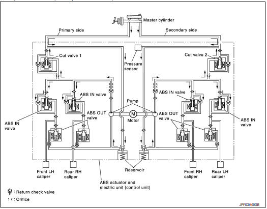
When ABS operation starts (when pressure holds)
|
Name |
Not activated |
When pressure holds |
| Cut valve 1 | Power supply is not supplied (open) | Power supply is not supplied (open) |
| Cut valve 2 | Power supply is not supplied (open) | Power supply is not supplied (open) |
| ABS IN valve | Power supply is not supplied (open) | Power supply is supplied (close) |
| ABS OUT valve | Power supply is not supplied (close) | Power supply is not supplied (close) |
| Each caliper (fluid pressure) |
— |
Pressure holds |
When front RH wheel caliper pressure holds
- Motor is activated. Brake fluid is pressurized by pump and is sent to secondary line through cut valve 2. At the same time, because ABS IN valve and ABS OUT vale are closed, fluid pressure holds.
When front LH wheel caliper pressure holds
- Motor is activated. Brake fluid is pressurized by pump and is sent to primary line through cut valve 1. At the same time, because ABS IN valve and ABS OUT vale are closed, fluid pressure holds.
When rear RH wheel caliper pressure holds
- Motor is activated. Brake fluid is pressurized by pump and is sent to primary line through cut valve 1. At the same time, because ABS IN valve and ABS OUT vale are closed, fluid pressure holds.
When rear LH wheel caliper pressure holds
- Motor is activated. Brake fluid is pressurized by pump and is sent to secondary line through cut valve 2. At the same time, because ABS IN valve and ABS OUT vale are closed, fluid pressure holds.
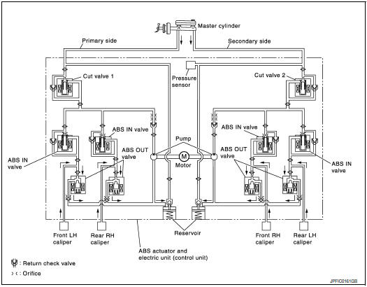
ABS is in operation (when pressure decreases)
|
Name |
Not activated |
When pressure decreases |
| Cut valve 1 | Power supply is not supplied (open) | Power supply is not supplied (open) |
| Cut valve 2 | Power supply is not supplied (open) | Power supply is not supplied (open) |
| ABS IN valve | Power supply is not supplied (open) | Power supply is supplied (close) |
| ABS OUT valve | Power supply is not supplied (close) | Power supply is supplied (open) |
| Each caliper (fluid pressure) |
— |
Pressure decreases |
When front RH wheel caliper pressure decreases
- Being supplied to reservoir through ABS OUT valve, the fluid pressure of brake caliper is decreased.
When front LH wheel caliper pressure decreases
- Being supplied to reservoir through ABS OUT valve, the fluid pressure of brake caliper is decreased.
When rear RH wheel caliper pressure decreases
- Being supplied to reservoir through ABS OUT valve, the fluid pressure of brake caliper is decreased.
When rear LH wheel caliper pressure decreases
- • Being supplied to reservoir through ABS OUT valve, the fluid pressure of brake caliper is decreased.
Component Parts and Function
|
Component |
FUNCTION |
| Reservoir | Temporarily reserves the brake fluid drained from brake caliper, so that pressure efficiently decreases when decreasing pressure of brake caliper. |
| Pump | Returns the brake fluid reserved in reservoir to master cylinder by reducing pressure. |
| Motor | Drives the pump according to signals from control unit. |
| ABS IN valve | Switches the fluid pressure line to increase or hold according to signals from control unit. |
| ABS OUT valve | Switches the fluid pressure line to increase, hold or decrease according to signals from control unit. |
| Return check valve | Returns the brake fluid from brake caliper to master cylinder by bypassing orifice of each valve when brake is released. |
| Cut valve 1 Cut valve 2 |
Performs the duty control of fluid pressure increased by pump according to signals from control unit. |
| Pressure Sensor | Detects the brake pedal operation amount. |
VALVE OPERATION (OTHER THAN ABS AND EBD)
Each valve is operated and fluid pressure of brake caliper is controlled.
NOTE: There is no operation to hold and increase pressure for functions other than ABS and EBD.
When Pressure Increases
|
Name |
Not activated |
When Pressure Increases |
| Cut valve 1 | Power supply is not supplied (open) | Wheel other than the one that the pressure is to be increased: Power supply is not supplied (open) Only wheel that the pressure is to be increased: Power supply is supplied (close) |
| Cut valve 2 | Power supply is not supplied (open) | Wheel other than the one that the pressure is to be increased: Power supply is not supplied (open) Only wheel that the pressure is to be increased: Power supply is supplied (close) |
| ABS IN valve | Power supply is not supplied (open) | Only wheel that the pressure is to be increased: Power supply is not supplied (open) Wheel other than the one that the pressure is to be increased: Power supply is supplied (close) |
| ABS OUT valve | Power supply is not supplied (close) | Power supply is not supplied (close) |
| Each caliper (fluid pressure) |
— |
Pressure increases |
When front RH wheel caliper pressure increases
- Motor is activated. Brake fluid from pump is supplied to front RH wheel caliper through ABS IN valve. For other wheel, ABS IN valve is closed and brakes fluid is not supplied to caliper.
When front LH wheel caliper pressure increases
- Motor is activated. Brake fluid from pump is supplied to front LH wheel caliper through ABS IN valve. For other wheel, ABS IN valve is closed and brakes fluid is not supplied to caliper.
When rear RH wheel caliper pressure increases
- Motor is activated. Brake fluid from pump is supplied to rear RH wheel caliper through ABS IN valve. For other wheel, ABS IN valve is closed and brakes fluid is not supplied to caliper.
When rear LH wheel caliper pressure increases
- Motor is activated. Brake fluid from pump is supplied to rear LH wheel caliper through ABS IN valve. For other wheel, ABS IN valve is closed and brakes fluid is not supplied to caliper.
Released

|
Name |
Not activated |
When Pressure Increases |
| Cut valve 1 | Power supply is not supplied (open) | Power supply is not supplied (open) |
| Cut valve 2 | Power supply is not supplied (open) | Power supply is not supplied (open) |
| ABS IN valve | Power supply is not supplied (open) | Power supply is not supplied (open) |
| ABS OUT valve | Power supply is not supplied (close) | Power supply is supplied (open) |
| Each caliper (fluid pressure) |
— |
Pressure decreases |
When front RH wheel caliper pressure decreases
- Being returned to master cylinder through ABS IN valve, fluid pressure of brake caliper is decreased.
When front LH wheel caliper pressure decreases
- Being returned to master cylinder through ABS IN valve, fluid pressure of brake caliper is decreased.
When rear RH wheel caliper pressure decreases
- Being returned to master cylinder through ABS IN valve, fluid pressure of brake caliper is decreased.
When rear LH wheel caliper pressure decreases
- Being returned to master cylinder through ABS IN valve, fluid pressure of brake caliper is decreased.
Component Parts and Function
|
Component |
Function |
| Reservoir | Temporarily reserves the brake fluid drained from brake caliper, so that pressure efficiently decreases when decreasing pressure of brake caliper. |
| Pump | Returns the brake fluid reserved in reservoir to master cylinder by reducing pressure. |
| Motor | Drives the pump according to signals from control unit. |
| ABS IN valve | Switches the fluid pressure line to increase or hold according to signals from control unit. |
| ABS OUT valve | Switches the fluid pressure line to increase, hold or decrease according to signals from control unit. |
| Return check valve | Returns the brake fluid from brake caliper to master cylinder by bypassing orifice of each valve when brake is released. |
| Cut valve 1 Cut valve 2 |
Performs the duty control of fluid pressure increased by pump according to signals from control unit. |
| Pressure Sensor | Detects the brake pedal operation amount. |
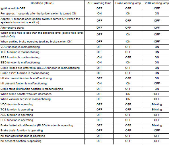
CONDITION FOR TURN ON THE WARNING LAMP
Turns ON when ignition switch turns ON and turns OFF when the system is normal, for bulb check purposes.
CONDITION FOR TURN ON THE INDICATOR LAMP
VDC OFF indicator lamp
- Turns ON when VDC function and TCS function are switched to non-operational status (OFF) by VDC OFF switch.
- Turns ON when ignition switch turns ON and turns OFF when the system is normal, for bulb check purposes.
|
Condition (status) |
VDC OFF indicator lamp |
| Ignition switch OFF. | OFF |
| For approx. 1 seconds after the ignition switch is turned ON. | ON |
| Approx. 1 seconds after ignition switch is turned ON (when the system is in normal operation). | OFF |
| When VDC OFF switch is ON (VDC function, TCS function and Active trace control function are OFF). | ON |
CONDITION FOR TURN ON THE INDICATOR LAMP
Hill descent indicator lamp
- Turns ON by the hill descent switch.
- Turns ON when ignition switch turns ON and turns OFF when the system is normal, for bulb check purposes.
|
Condition (status) |
Hill Descent indicator lamp |
| Ignition switch OFF. | OFF |
| For approx. 1 seconds after the ignition switch is turned ON. | ON |
| Approx. 1 seconds after ignition switch is turned ON (when the system is in normal operation). | OFF |
| When hill descent switch is ON. | ON |
| When hill descent control switch is on, but the system is not engaged. | Blinking |
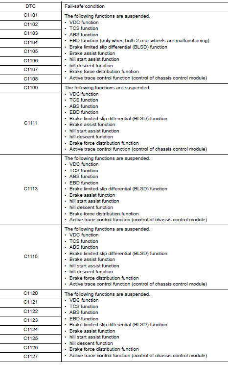
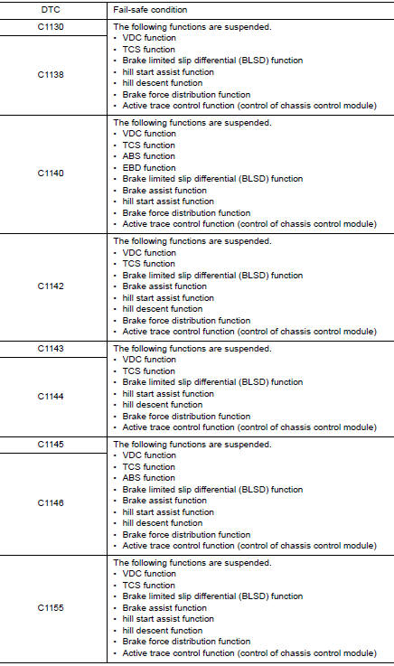
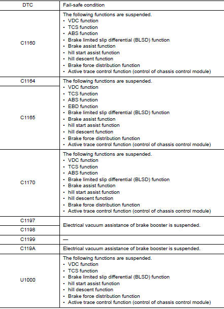
Fail-Safe
VDC FUNCTION, TCS FUNCTION, BRAKE LIMITED SLIP DIFFERENTIAL FUNCTION, BRAKE ASSIST FUNCTION, hill start assist FUNCTION, hill descent FUNCTION AND BRAKE FORCE DISTRIBUTION FUNCTION
VDC warning lamp in combination meter turn ON when a malfunction occurs in system [ABS actuator and electric unit (control unit)]. The control is suspended for VDC function, TCS function, Brake limited slip differential (BLSD) function, Brake assist function, hill start assist function and Brake force distribution function. The vehicle status becomes the same as models without VDC function, TCS function, Brake limited slip differential (BLSD) function, Brake assist function, hill start assist function and Brake force distribution function. However, ABS function and EBD function are operated normally.
ABS FUNCTION
ABS warning lamp and VDC warning lamp in combination meter turn ON when a malfunction occurs in system [ABS actuator and electric unit (control unit)]. The control is suspended for VDC function, TCS function, ABS function, Brake limited slip differential (BLSD) function, Brake assist function, hill start assist function and Brake force distribution function. The vehicle status becomes the same as models without VDC function, TCS function, ABS function, Brake limited slip differential (BLSD) function, Brake assist function, hill start assist function and Brake force distribution function. However, EBD function is operated normally.
NOTE: ABS self-diagnosis sound may be heard the same as in the normal condition, because self-diagnosis is performed when ignition switch turns ON and when vehicle initially starts.
EBD FUNCTION
ABS warning lamp, brake warning lamp and VDC warning lamp in combination meter turn ON when a malfunction occurs in system [ABS actuator and electric unit (control unit)]. The control is suspended for VDC function, TCS function, ABS function, EBD function, Brake limited slip differential (BLSD) function, Brake assist function, hill start assist function and Brake force distribution function. The vehicle status becomes the same as models without VDC function, TCS function, ABS function, EBD function, Brake limited slip differential (BLSD) function, Brake assist function, hill start assist function and Brake force distribution function.
VDC FUNCTION
VDC FUNCTION : System Description
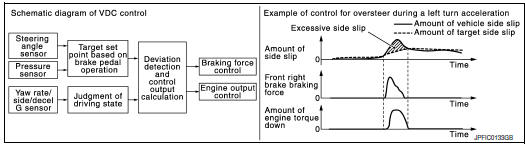
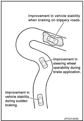
- Side slip or tail slip may occur while driving on a slippery road or intending an urgent evasive driving. VDC function detects side slip status using each sensor when side slip or tail slip is about to occur and improves vehicle stability by brake control and engine output control during driving.
- In addition to ABS function, EBD function and TCS function, target side slip amount is calculated according to steering operation amount from steering angle sensor and brake operation amount from brake pressure sensor. By comparing this information with vehicle side slip amount that is calculated from information from yaw rate/side/decel G sensor and wheel sensor, vehicle driving conditions (conditions of understeer or oversteer) are judged and vehicle stability is improved by brake force control on all 4 wheels and engine output control.
- VDC function can be switched to non-operational status (OFF) by operating VDC OFF switch. In this case, VDC OFF indicator lamp turns ON.
- Control unit portion automatically improves driving stability by performing brake force control as well as engine output control, by transmitting drive signal to actuator portion according to difference between target side slip amount and vehicle side slip amount
- VDC warning lamp blinks while VDC function is in operation and indicates to the driver that the function is in operation.
- CONSULT can be used to diagnose the system diagnosis.
- Fail-safe function is adopted. When a malfunction occurs in VDC
function, the control is suspended for VDC
function, TCS function, Brake limited slip differential (BLSD) function,
Brake assist function, hill start assist
function and Brake force distribution function. The vehicle status becomes
the same as models without VDC
function, TCS function, Brake limited slip differential (BLSD) function,
Brake assist function, hill start assist
function and Brake force distribution function. However, ABS function and
EBD function are operated normally.
Refer to BRC-22, "Fail-Safe".
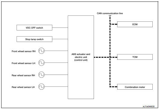
SYSTEM DIAGRAM
INPUT SIGNAL AND OUTPUT SIGNAL
Major signal transmission between each unit via communication lines is shown in the following table.
|
Component |
Signal description |
| ECM | Mainly transmits the following signals to ABS actuator and electric
unit (control unit) via CAN
communication:
Mainly receives the following signal from ABS actuator and electric unit (control unit) via CAN communication:
|
| TCM | Mainly transmits the following signal to ABS actuator and electric
unit (control unit) via CAN
communication:
|
| Chassis control module | Mainly transmits the following signal to ABS actuator and electric
unit (control unit) via CAN
communication:
|
| Combination meter | Mainly receives the following signals from ABS actuator and electric
unit (control unit) via CAN
communication:
Mainly receives the following signals from ABS actuator and electric unit (control unit) via CAN communication:
|
| Steering angle sensor | Mainly transmits the following signals to ABS actuator and electric
unit (control unit) via CAN
communication:
|
OPERATION CHARACTERISTICS
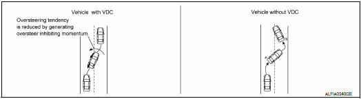
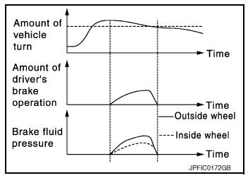
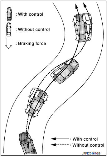
VDC Function That Prevents Oversteer Tendency
- During a cornering, brake force (brake fluid pressure) is applied on front wheel and rear wheel on the outer side of turn. Momentum directing towards the outer side of turn is generated. Oversteer is prevented.
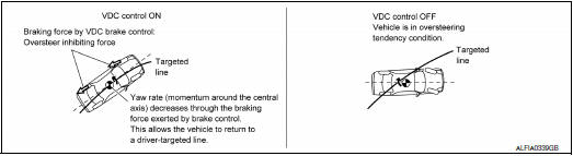
- Changing driving lane on a slippery road, when oversteer tendency is judged large, engine output is controlled as well as brake force (brake fluid pressure) of 4 wheels. Oversteer tendency decreases.
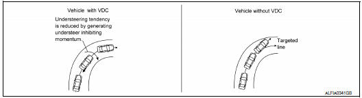
VDC Function That Prevents Understeer Tendency
- During a cornering, brake force (brake fluid pressure) is applied on front wheel and rear wheel on the inner side of turn. Momentum directing towards the inner side of turn is generated. Understeer is prevented.
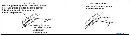
- Applying braking during a cornering on a slippery road, when understeer tendency is judged large, engine output is controlled as well as brake force (brake fluid pressure) of four wheels. Understeer tendency decreases.
TCS FUNCTION
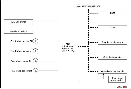
TCS FUNCTION : System Description
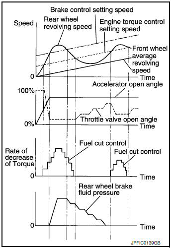
- Wheel spin status of drive wheel is detected by wheel sensor of 4 wheels. Engine output and transmission shift status is controlled so that slip rate of drive wheels is in appropriate level. When wheel spin occurs on drive wheel, ABS actuator and electric unit (control unit) perform brake force control of LH and RH drive wheels (apply brake force by increasing brake fluid pressure of drive wheel) and decrease engine torque by engine torque control. Wheel spin amount decreases. Engine torque is controlled to appropriate level.
- TCS function can be switched to non-operational status (OFF) by operating VDC OFF switch. In this case, VDC OFF indicator lamp turns ON.
- VDC warning lamp blinks while TCS function is in operation and indicates to the driver that the function is in operation.
- CONSULT can be used to diagnose the system diagnosis.
- Fail-safe function is adopted. When a malfunction occurs in TCS function, the control is suspended for VDC function, TCS function, Brake limited slip differential (BLSD) function, Brake assist function, hill start assist function and Brake force distribution function The vehicle status becomes the same as models without VDC function, TCS function, Brake limited slip differential (BLSD) function, Brake assist function, hill start assist function and Brake force distribution function However, ABS function and EBD function are operated normally. Refer to BRC-22, "Fail-Safe".
SYSTEM DIAGRAM
INPUT SIGNAL AND OUTPUT SIGNAL
Major signal transmission between each unit via communication lines is shown in the following table.
|
Component |
Signal description |
| ECM | Mainly transmits the following signals to ABS actuator and electric
unit (control unit) via CAN
communication:
Mainly receives the following signal from ABS actuator and electric unit (control unit) via CAN communication:
|
| TCM | Mainly transmits the following signal to ABS actuator and electric
unit (control unit) via CAN
communication:
|
| Chassis control module | Mainly transmits the following signal to ABS actuator and electric
unit (control unit) via CAN
communication:
|
| Combination meter | Mainly receives the following signals from ABS actuator and electric
unit (control unit) via CAN
communication:
Mainly receives the following signals from ABS actuator and electric unit (control unit) via CAN communication:
|
| Steering angle sensor | Mainly transmits the following signals to ABS actuator
and electric unit (control unit) via CAN
communication:
|
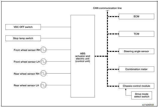
ABS FUNCTION : System Description
- By preventing wheel lock through brake force (brake fluid pressure) control that is electronically controlled by detecting wheel speed during braking, stability during emergency braking is improved so that obstacles can be easily bypassed by steering operation.
- During braking, control units calculates wheel speed and pseudo-vehicle speed, and transmits pressure increase, hold or decrease signals to actuator portion according to wheel slip status.
- The following effects are obtained by preventing wheel lock during braking.
- Vehicle tail slip is prevented during braking when driving straight.
- Understeer and oversteer tendencies are moderated during braking driving on a corner.
- Obstacles may be easily bypassed by steering operation during braking.
- CONSULT can be used to diagnose the system diagnosis.
- Fail-safe function is adopted. When a malfunction occurs in ABS function, the control is suspended for VDC function, TCS function, ABS function, Brake limited slip differential (BLSD) function, Brake assist function, hill start assist function and Brake force distribution function. The vehicle status becomes the same as models without VDC function, TCS function, ABS function, Brake limited slip differential (BLSD) function, Brake assist function, hill start assist function and Brake force distribution function. However, EBD function is operated normally. Refer to BRC-22, "Fail-Safe".
NOTE:
- ABS has the characteristic as described here, This is not the device that helps reckless driving.
- To stop vehicle efficiently, ABS does not operate and ordinary brake operates at low speed [approx. 10 km/h (6 MPH) or less, but differs subject to road conditions).
- Self-diagnosis is performed immediately after when engine starts and when vehicle initially is driven [by vehicle speed approx. 15 km/h (9 MPH)]. Motor sounds are generated during self-diagnosis. In addition, brake pedal may be felt heavy when depressing brake pedal lightly. These symptoms are not malfunctions.
SYSTEM DIAGRAM
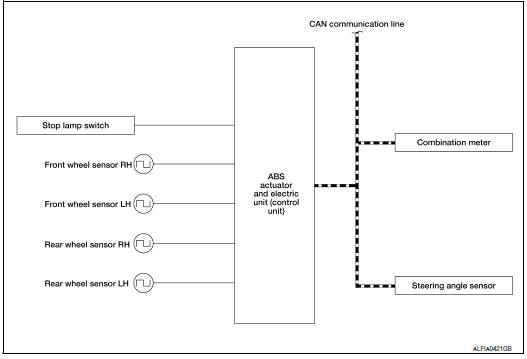
INPUT SIGNAL AND OUTPUT SIGNAL
Major signal transmission between each unit via communication lines is shown in the following table.
|
Component |
Signal description |
| Combination meter | Mainly receives the following signals from ABS actuator and electric
unit (control unit) via CAN
communication:
Mainly receives the following signals from ABS actuator and electric unit (control unit) via CAN communication:
|
| Steering angle sensor | Mainly transmits the following signals to ABS actuator and electric
unit (control unit) via CAN
communication:
|
EBD FUNCTION
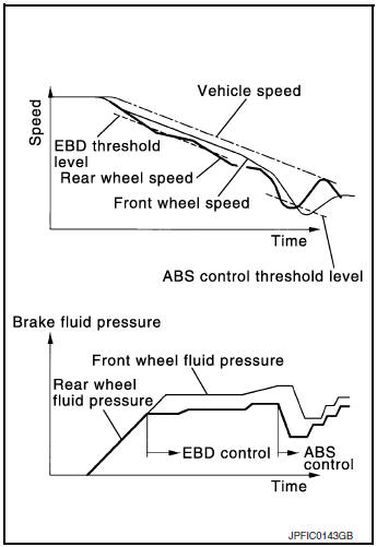
EBD FUNCTION : System Description
- By preventing rear wheel slip increase through rear wheel brake force (brake fluid pressure) control that is electronically controlled when slight skip on front and rear wheels are detected during braking, stability during braking is improved.
- EBD function is expanded and developed from conventional ABS function and corrects rear wheel brake force to appropriate level by electronic control according to load weight (number of passengers).
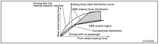
- During braking, control unit portion compares slight slip on front and rear wheels by wheel speed sensor signal, transmits drive signal to actuator portion when rear wheel slip exceeds front wheel slip for the specified value or more, and controls rear wheel brake force (brake fluid pressure) so that increase of rear wheel slip is prevented and slips on front wheel and rear wheel are nearly equalized. ABS control is applied when slip on each wheel increases and wheel speed is the threshold value of ABS control or less.
- CONSULT can be used to diagnose the system diagnosis.
- Fail-safe function is adopted. When a malfunction occurs in EBD function, the control is suspended for VDC function, TCS function, ABS function, EBD function, Brake limited slip differential (BLSD) function, Brake assist function, hill start assist function and Brake force distribution function. The vehicle status becomes the same as models without VDC function, TCS function, ABS function, EBD function, Brake limited slip differential (BLSD) function, Brake assist function, hill start assist function and Brake force distribution function. Refer to BRC-22, "Fail-Safe".
SYSTEM DIAGRAM
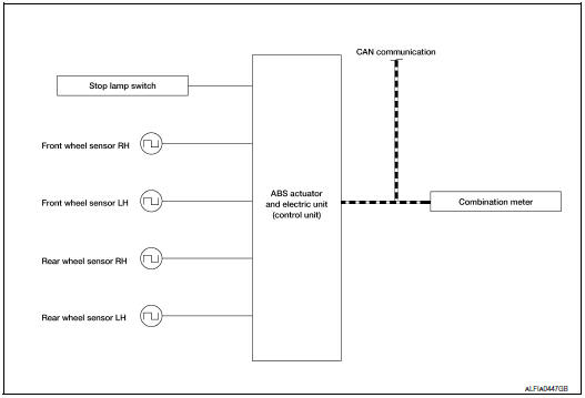
INPUT SIGNAL AND OUTPUT SIGNAL
Major signal transmission between each unit via communication lines is shown in the following table.
|
Component |
Signal description |
| Combination meter | Mainly receives the following signals from ABS actuator and electric
unit (control unit) via CAN
communication:
|
BRAKE LIMITED SLIP DIFFERENTIAL (BLSD) FUNCTION
BRAKE LIMITED SLIP DIFFERENTIAL (BLSD) FUNCTION : System Description
- LH and RH driving wheel spin is always monitored. If necessary, appropriate brake force is independently applied to LH or RH driving wheel so that one-sided wheel spin is avoided and traction is maintained. Mainly starting ability is improved.
- Brake limited slip differential (BLSD) function operates while VDC function is in non-operational status (OFF) by VDC OFF switch.
- VDC warning lamp blinking while Brake limited slip differential (BLSD) function is in operation and indicates to the driver that the function is in operation.
- Slight vibrations are felt on the Brake pedal and the operation noises occur, when Brake limited slip differential (BLSD) function operates. This is not a malfunction because it is caused by Brake limited slip differential (BLSD) function that is normally operated.
- Fail-safe function is adopted. When a malfunction occurs in brake limited slip differential (BLSD) function, the control is suspended for VDC function, TCS function, Brake limited slip differential (BLSD) function, Brake assist function, hill start assist function and Brake force distribution function. The vehicle status becomes the same as models without VDC function, TCS function, Brake limited slip differential (BLSD) function, Brake assist function, hill start assist function and Brake force distribution function. However, ABS function and EBD function are operated normally. Refer to BRC-22, "Fail-Safe".
SYSTEM DIAGRAM
INPUT SIGNAL AND OUTPUT SIGNAL
Major signal transmission between each unit via communication lines is shown in the following table.
|
Component |
Signal description |
| ECM | Mainly transmits the following signals to ABS actuator and electric
unit (control unit) via CAN
communication:
Mainly receives the following signal from ABS actuator and electric unit (control unit) via CAN communication:
|
| TCM | Mainly transmits the following signal to ABS actuator and electric
unit (control unit) via CAN
communication:
|
| Chassis control module | Mainly transmits the following signal to ABS actuator and electric
unit (control unit) via CAN
communication:
|
| Combination meter | Mainly receives the following signals from ABS actuator and electric
unit (control unit) via CAN
communication:
Mainly receives the following signals from ABS actuator and electric unit (control unit) via CAN communication:
|
| Steering angle sensor | Mainly transmits the following signals to ABS actuator and electric
unit (control unit) via CAN
communication:
|
BRAKE ASSIST FUNCTION
BRAKE ASSIST FUNCTION : System Description
- When the driver brakes hard in an emergency, the stopping distance is reduced by increasing brake fluid pressure.
- Fail-safe function is adopted. When a malfunction occurs in Brake assist function, the control is suspended for VDC function, TCS function, Brake limited slip differential (BLSD) function, Brake assist function, hill start assist function and Brake force distribution function. The vehicle status becomes the same as models without VDC function, TCS function, Brake limited slip differential (BLSD) function, Brake assist function, hill start assist function and Brake force distribution function. However, ABS function and EBD function are operated normally. Refer to BRC-22, "Fail-Safe".
SYSTEM DIAGRAM
INPUT SIGNAL AND OUTPUT SIGNAL
Major signal transmission between each unit via communication lines is shown in the following table.
|
Component |
Signal description |
| ECM | Mainly transmits the following signal to ABS actuator and electric
unit (control unit) via CAN
communication:
Mainly receives the following signal from ABS actuator and electric unit (control unit) via CAN communication:
|
| TCM | Mainly transmits the following signal to ABS actuator and electric
unit (control unit) via CAN
communication:
|
| Chassis control module | Mainly transmits the following signal to ABS actuator and electric
unit (control unit) via CAN
communication:
|
| Combination meter | Mainly receives the following signals from ABS actuator and electric
unit (control unit) via CAN
communication:
Mainly receives the following signals from ABS actuator and electric unit (control unit) via CAN communication:
|
| Combination meter | Mainly transmits the following signals to ABS actuator and electric
unit (control unit) via CAN
communication:
|
hill descent control (Downhill Drive Support) FUNCTION
hill descent control (Downhill Drive Support) FUNCTION : System Diagram
hill descent control (Downhill Drive Support) FUNCTION : System Description
- The hill descent control system will help maintain vehicle speed when
driving on steeper downhill grades.
Hill descent control will provide braking allowing the driver to concentrate on steering while reducing the burden of brake and accelerator operation.
- To operate the system, push the hill descent control switch. the hill descent control indicator in the combination meter will turn on
- Hill start assist function is only for the start aid. It maintains the brake fluid pressure for approx. 2 seconds after releasing the brake pedal, and then decreases the pressure gradually. If the vehicle starts by the accelerator operation, the brake is released automatically and a smooth start can be performed.
- Fail-safe function is adopted. When a malfunction occurs in hill start assist function, the control is suspended for VDC function, TCS function, hill start assist function, Brake force distribution function and Active trace control function. The vehicle status becomes the same as models without VDC function, TCS function, hill start assist function, Brake force distribution function and Active trace control function. However, ABS function and EBD function are operated normally. Refer to BRC-51, "Fail-Safe".
INPUT SIGNAL AND OUTPUT SIGNAL
Major signal transmission between each unit via communication lines is shown in the following table.
|
Component |
Signal description |
| Yaw rate/side/decel G sensor | Mainly transmits the following signals to ABS actuator and electric
unit (control unit) via communication
line *:
|
| ECM | Mainly transmits the following signals to ABS actuator and electric
unit (control unit) via CAN
communication:
Mainly receives the following signal from ABS actuator and electric unit (control unit) via CAN communication:
|
| TCM | Mainly transmits the following signal to ABS actuator and electric
unit (control unit) via CAN
communication:
|
| Combination meter | Mainly transmits the following signals to ABS actuator and electric
unit (control unit) via CAN
communication:
Mainly receives the following signals from ABS actuator and electric unit (control unit) via CAN communication:
|
*: Communication line between yaw rate/side/decel G sensor and ABS actuator and electric unit (control unit)
hill start assist FUNCTION
hill start assist FUNCTION : System Description
- This function maintains brake fluid pressure so that the vehicle does not move backwards even if brake pedal is released to depress accelerator pedal to start the vehicle while it is stopped on an uphill slope by depressing brake pedal.
- This function operates when the vehicle is in stop status on a uphill slope of slope ratio 10% or more and selector lever is in the position other than P or N.
- hill start assist function is only for the start aid. It maintains the brake fluid pressure for approx. 2 seconds after releasing the brake pedal, and then decreases the pressure gradually. If the vehicle can start by the accelerator operation, the brake is released automatically and a smooth start can be performed.
- Fail-safe function is adopted. When a malfunction occurs in hill start assist function, the control is suspended for VDC function, TCS function, Brake limited slip differential (BLSD) function, Brake assist function, hill start assist function and Brake force distribution function. The vehicle status becomes the same as models without VDC function, TCS function, Brake limited slip differential (BLSD) function, Brake assist function, hill start assist function and Brake force distribution function. However, ABS function and EBD function are operated normally. Refer to BRC-22, "Fail-Safe".
SYSTEM DIAGRAM
INPUT SIGNAL AND OUTPUT SIGNAL
Major signal transmission between each unit via communication lines is shown in the following table.
|
Component |
Signal description |
| ECM | Mainly transmits the following signals to ABS actuator and electric
unit (control unit) via CAN
communication:
Mainly receive: the following signal from ABS actuator and electric unit (control unit) via CAN communication:
|
| TCM | Mainly transmits the following signal to ABS actuator and electric
unit (control unit) via CAN
communication:
|
| Combination meter | Mainly receives the following signals from ABS actuator and electric
unit (control unit) via CAN
communication:
Mainly receives the following signals from ABS actuator and electric unit (control unit) via CAN communication:
|
BRAKE FORCE DISTRIBUTION FUNCTION
BRAKE FORCE DISTRIBUTION FUNCTION : System Description
- Brake force distribution function is controlled by ABS actuator and electric unit (control unit).
- Brake force distribution function helps provide a more stable and secure feeling.
- During cornering, when brake operation is performed brake fluid pressure of each wheel is controlled based on steering operation amount by the driver and vehicle cornering status amount detected by each sensor.
- Fail-safe function is adopted. When a malfunction occurs in Brake
force distribution function, the control is suspended for VDC function,
TCS function, Brake limited slip differential (BLSD) function,
Brake assist function, hill start assist function and Brake force
distribution
function. The vehicle status becomes the same as models
without VDC function, TCS function, Brake limited slip differential
(BLSD) function, Brake assist function, hill start assist function and
Brake force distribution function. However, ABS function and EBD
function are operated normally. Refer to BRC-22, "Fail-Safe".
NOTE: Brake force distribution function may not always be operates in all driving conditions.
SYSTEM DIAGRAM
INPUT SIGNAL AND OUTPUT SIGNAL
Major signal transmission between each unit via communication lines is shown in the following table.
|
Component |
Signal description |
| ECM | Mainly transmits the following signals to ABS actuator and electric
unit (control unit) via CAN
communication:
Mainly receives the following signals from ABS actuator and electric unit (control unit) via CAN communication.
|
| TCM | Mainly transmits the following signal to ABS actuator and electric
unit (control unit) via CAN
communication:
|
| Chassis control module | Mainly transmits the following signal to ABS actuator and electric
unit (control unit) via CAN
communication:
|
| Combination meter | Mainly receives the following signals from ABS actuator and electric
unit (control unit) via CAN
communication:
Mainly receives the following signals from ABS actuator and electric unit (control unit) via CAN communication:
|
| Steering angle sensor | Mainly transmits the following signals to ABS actuator and electric
unit (control unit) via CAN
communication:
|
ACTIVE TRACE CONTROL FUNCTION
ACTIVE TRACE CONTROL FUNCTION : System Description
- Active trace control function controls the braking utilizing the ABS actuator and electric unit (control unit), depending on cornering condition calculated from driver's steering input and plural sensors.
- Active trace control function is aimed to enhance traceability at corners and smooth the vehicle movement to provide confident driving.
- When the drive mode select switch is set to the “SPORT” mode, the amount of brake control provided by active trace control is reduced.
- For “PERSONAL” mode, the active trace control can be selected ON or OFF. Refer to BRC-39, "ACTIVE TRACE CONTROL FUNCTION : System Description".
- When the VDC OFF switch is used to turn OFF the VDC system, the active trace control system is also turned OFF.
- When the active trace control is operated, active trace control
graphics are shown on the information display
of combination meter. These are shown only when “Chassis control” is
selected on the information display.
Refer to DAS-175, "System Description - Chassis Control".
- When the active trace control is not functioning properly, the master warning lamp illuminates. Warning message “Chassis control” will also appear on information display.
NOTE:
- The active trace control may not be effective depending on the driving condition. Always driving carefully and attentively.
- Brake pedal may vibrate and brake pedal feel may change during active trace control operation. Also operation noise may be noticeable during operation. These are not abnormal conditions.
- When the active trace control is selected OFF, some functions will be kept ON to assist driver. (For example, avoidance condition.)
OPERATION CHARACTERISTICS
Active trace control helps enhance the transition from braking into and then accelerating out of corners. Active trace control utilizes the vehicle′s electrically-driven intelligent brake system to help improve cornering feel by automatically applying brakes. Furthermore, Active trace control will apply selective braking to help create increased steering response in S-turns. For example, if driving through an Sturn that starts with steering to the right, the right-side brakes are engaged to create a yaw momentum and help turn the vehicle.
- Brake control amount is controlled according to steering operation status by the driver and vehicle cornering status.
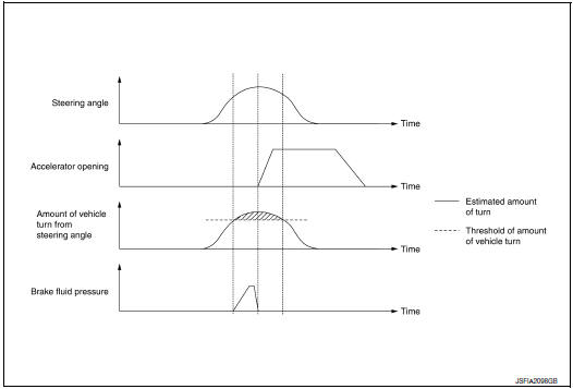
- During cornering, the brake control system limits changes in steering angle by controlling the inner ring brakes according to accelerator pedal operation and allows smooth movement of the vehicle to achieve stable cornering.

SYSTEM DIAGRAM
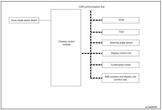
INPUT SIGNAL AND OUTPUT SIGNAL
Major signal transmission between each unit via communication lines is shown in the following table.
|
Component |
Signal description |
| ECM | Mainly transmits the following signals to chassis control module via
CAN communication:
|
| ECM | Mainly transmits the following signal to chassis control module via
CAN communication:
|
| ABS actuator and electric unit (control unit) | Mainly transmits the following signals to chassis control module via
CAN communication:
Mainly receives the following signal from chassis control module via CAN communication:
|
| Steering angle sensor | Mainly transmits the following signal to chassis control module via
CAN communication:
|
| Chassis control module | Mainly transmits the following signals to ABS actuator and electric
unit (control unit) via CAN
communication:
|
| Display control unit | Mainly transmits the following signal to chassis control module via
CAN communication line:
|
| Combination meter | Mainly receives the following signals from chassis control module
via CAN communication.
|
| Drive mode select switch | Mainly transmits the following signal to chassis control module:
|
WARNING/INDICATOR/CHIME LIST
WARNING/INDICATOR/CHIME LIST : Warning Lamp/Indicator Lamp
| Name | Design | Layout/Function |
| ABS warning lamp |
|
For function: Refer to BRC-119, "Component Function Check". |
| Brake warning lamp |
|
For function: Refer to BRC-120, "Component Function Check". |
| VDC OFF indicator lamp |
|
For function: Refer to BRC-123, "Component Function Check". |
| VDC warning lamp |
|
For function: Refer to BRC-122, "Component Function Check". |


 Component parts
Component Parts Location
Steering column (view with steering
wheel removed)
RH side of instrument panel (view with
instrument panel removed)
LH side of engine compartment
RH si ...
 Diagnosis system [ABS actuator and electric unit (control
unit)]
Diagnosis system [ABS actuator and electric unit (control
unit)]
CONSULT Function
APPLICATION ITEMS
CONSULT can display each diagnostic item using the diagnostic test modes as
follows.
Mode
Function description
ECU identification
...
Other materials:
Second row seats
Exploded View
RH SEAT
Headrest
Seatback upper luggage
board
Seatback luggage board
Seatback trim
Seatback pad
Recline release cable
Seat cushion trim
Fold flat strap
Seat cushion pad
Seat cushion silencer
Bolt cover
Seat cushion outer f ...
Air conditioner system refrigerant and oil recommendations
The air conditioner system in your NISSAN
vehicle must be charged with the refrigerant
HFC-134a (R-134a) and NISSAN A/C
system oil Type ND-OIL8 or the exact
equivalents.
CAUTIONThe use of any other refrigerant or oil will
cause severe damage to the air conditioning
system and will ...
P0705 transmission range sensor A
DTC Description
DTC DETECTION LOGIC
DTC
CONSULT screen terms
(Trouble diagnosis content)
DTC detection condition
P0705
T/M RANGE SENSOR A
[Transmission Range Sensor A Circuit (PRNDL
Input)]
When all of the following conditions are satisfied and this state is
...
