Nissan Rogue Service Manual: Component parts
Component Parts Location
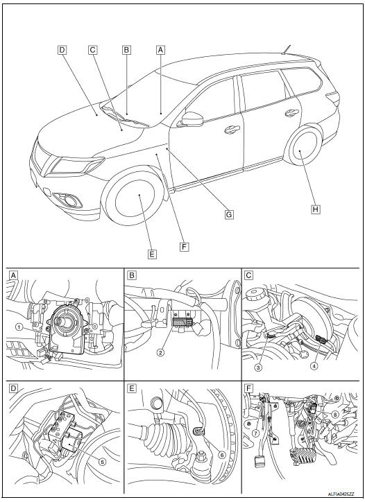
- Steering column (view with steering wheel removed)
- RH side of instrument panel (view with instrument panel removed)
- LH side of engine compartment
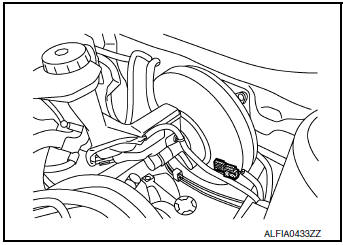
- RH side of engine compartment
- Left front wheel area
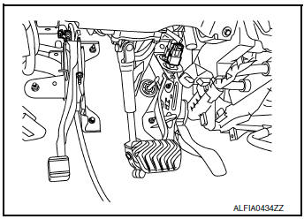
- Brake pedal area
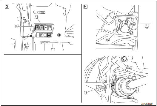
- Left side of instrument panel
- Left rear wheel area
| No. | Component parts | Function |
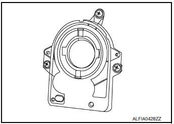
| 1 | Steering angle sensor | BRC-12, "Steering Angle Sensor" |
| 2 | Chassis control module | Mainly transmits the following signals to ABS actuator and electric
unit (control
unit) via CAN communication.
Refer to DAS-173, "Component Parts Location" for detailed installation location. |
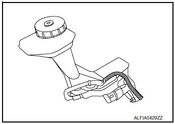
| 3 | Brake fluid level switch | BRC-12, "Brake Fluid Level Switch" |
| 4 | Vacuum sensor | BRC-13, "Vacuum Sensor" |
| 5 | ABS actuator and electric unit (control unit) | BRC-11, "ABS Actuator and Electric Unit (Control Unit)" |
| 6 | Front LH wheel sensor | BRC-10, "Wheel Sensor and Sensor Rotor" |
| 7 | Parking brake switch | BRC-13, "Parking Brake Switch" |
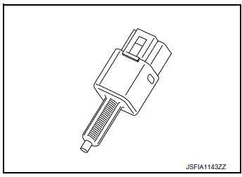
| 8 | Stop lamp switch | BRC-13, "Parking Brake Switch" |
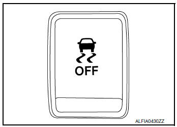
| 9 | VDC OFF switch | BRC-13, "VDC OFF Switch" |
| 10 | Drive mode switch | DMS-4, "SPORT Mode Switch" |
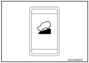
| 11 | Hill decent switch | BRC-13, "Hill Descent Control Switch" |
| 12 | Rear LH wheel sensor | BRC-10, "Wheel Sensor and Sensor Rotor" |
| 13 | Rear LH wheel sensor (with AWD) | BRC-10, "Wheel Sensor and Sensor Rotor" |
Wheel Sensor and Sensor Rotor
NOTE:
- Wheel sensor of front wheel is installed on steering knuckle.
- Sensor rotor of front wheel is integrated in wheel hub assembly.
- Wheel sensor of rear wheel is installed on rear final drive.
- Sensor rotor of rear wheel is installed on drive shaft (rear final drive side).
- Never measure resistance and voltage value using a tester because sensor is active sensor.
- Power supply is supplied to detection portion so that magnetic field line is read. Magnetic field that is detected is converted to current signal.
- When sensor rotor rotates, magnetic field changes. Magnetic field change is converted to current signals (rectangular wave) and is transmitted to ABS actuator and electric unit (control unit). Change of magnetic field is proportional to wheel speed.
ABS Actuator and Electric Unit (Control Unit)
Electric unit (control unit) is integrated with actuator and comprehensively controls VDC function, TCS function, ABS function, EBD function, Brake limited slip differential (BLSD) function, Brake assist function, hill start assist function and Brake force distribution function.
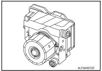
ELECTRIC UNIT (CONTROL UNIT)
- Brake fluid pressure, engine and transmission are controlled according to signals from each sensor.
- If malfunction is detected, the system enters fail-safe mode.
ACTUATOR
The following components are integrated with ABS actuator.
Pump
Returns the brake fluid reserved in reservoir to master cylinder by reducing pressure.
Motor
Activates the pump according to signals from ABS actuator and electric unit (control unit).
Motor Relay
Operates the motor ON/OFF according to signals from ABS actuator and electric unit (control unit).
Actuator Relay
Operates each valve ON/OFF according to signals from ABS actuator and electric unit (control unit).
ABS IN Valve and ABS OUT Valve
Increases, holds or decreases the fluid pressure of each caliper according to signals from ABS actuator and electric unit (control unit).
Pressure Sensor
Detects the brake fluid pressure and transmits signal to ABS actuator and electric unit (control unit).
Cut Valve 1 (Primary Line), Cut Valve 2 (Secondary Line)
Shuts off the ordinary brake line from master cylinder, when VDC function, TCS function, Brake limited slip differential (BLSD) function, Brake assist function, hill start assist function and Brake force distribution function are activated.
Yaw Rate/Side/Decel G Sensor
Calculates the following information that affects the vehicle, and transmits a signal to ABS actuator and electric unit (control unit). [Yaw rate/side/decel G sensor is integrated in ABS actuator and electric unit (control unit).]
- Vehicle rotation angular velocity (yaw rate signal)
- Vehicle lateral acceleration (side G signal)
- Vehicle longitudinal acceleration (decel G signal)
Stop Lamp Switch
Detects the operation status of brake pedal and transmits converted electric signal to ABS actuator and electric unit (control unit).
Steering Angle Sensor
Detects the following information and transmits steering angle signal to ABS actuator and electric unit (control unit) via CAN communication.
- Steering angle sensor malfunction signal
- Steering wheel rotation amount
- Steering wheel rotation angular velocity
- Steering wheel rotation direction
Brake Fluid Level Switch
Detects the brake fluid level in reservoir tank and transmits converted electric signal from combination meter to ABS actuator and electric unit (control unit) via CAN communication, when brake fluid level is the specified level or less.
Vacuum Sensor
Detects the vacuum in brake booster and transmits converted electric signal to ABS actuator and electric unit (control unit).
Parking Brake Switch
Detects the operation status of parking brake switch and transmits converted electric signal from combination meter to ABS actuator and electric unit (control unit).
VDC OFF Switch
- This is an integrated switch with switches for other functions.
- Non-operational status or standby status of the following functions can be selected using VDC OFF switch. VDC OFF indicator lamp indicates the operation status of function. (ON: Non-operational status, OFF: Standby status)
- VDC function
- TCS function
- Active trace control function
NOTE: ABS function, EBD function and Brake limited slip differential (BLSD) function control operates.
- VDC OFF indicator lamp turns OFF (standby status) when the engine is started again after it is stopped once while VDC OFF indicator lamp is ON (non-operational status).
Hill Descent Control Switch
- The hill descent control system will help maintain vehicle speed on steeper downhill grades. Hill descent control will provide braking allowing the driver to concentrate on steering while reducing the burden and accelerator operation.

 System
System Description
The system switches fluid pressure of each brake caliper to increase, to
hold or to decrease according to
signals from control unit in ABS actuator and electric unit (contr ...
Other materials:
P0506 ISC system
Description
The ECM controls the engine idle speed to a specified level through the fine
adjustment of the air, which is let
into the intake manifold, by operating the electric throttle control actuator.
The operating of the throttle valve is
varied to allow for optimum control of the engine ...
Wheel sensor
FRONT WHEEL SENSOR
FRONT WHEEL SENSOR : Exploded View
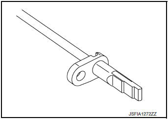
Front LH wheel sensor
Harness connector
Slant line
FRONT WHEEL SENSOR : Removal and Installation
CAUTION:
Be careful not to damage front wheel sensor edge and sensor
rotor teeth.
When removing the front ...
Sensor rotor
FRONT SENSOR ROTOR
FRONT SENSOR ROTOR : Removal and Installation - Front Sensor Rotor
The front wheel sensor rotor is an integral part of the wheel hub and bearing
and cannot be disassembled.
Refer to FAX-9, "Removal and Installation" (FWD) or FAX-40, "Removal and
Installatio ...
