Nissan Rogue Service Manual: P1078 EVT control position sensor
DTC Description
DTC DETECTION LOGIC
| DTC No. | CONSULT screen terms (Trouble diagnosis content) | DTC detecting condition |
| P1078 | EXH TIM SEN/CIRC-B1 (EXH TIM SEN/CIRC-B1) | An excessively high or low voltage from the sensor is sent to ECM. |
POSSIBLE CAUSE
- Harness or connectors (Exhaust valve timing control position sensor circuit is open or shorted.)
- Accumulation of debris to the signal pick-up portion of the camshaft
- Exhaust valve timing control position sensor
- Sensor power supply 2 circuit
FAIL-SAFE
- Traveling control mode (Accelerator angle variation control)
- Device fix mode
DTC CONFIRMATION PROCEDURE
1.PRECONDITIONING
If DTC Confirmation Procedure has been previously conducted, always perform the following procedure before conducting the next test.
- Turn ignition switch OFF and wait at least 10 seconds.
- Turn ignition switch ON.
- Turn ignition switch OFF and wait at least 10 seconds.
>> GO TO 2.
2.PERFORM DTC CONFIRMATION PROCEDURE
- Start engine and let it idle for 10 seconds.
- Check 1st trip DTC.
Is 1st trip DTC detected? YES >> Proceed to EC-385, "Diagnosis Procedure".
NO >> INSPECTION END
Diagnosis Procedure
1.CHECK EXHAUST VALVE TIMING (EVT) CONTROL POSITION SENSOR POWER SUPPLY
- Turn ignition switch OFF.
- Disconnect exhaust valve timing (EVT) control position sensor harness connector.
- Turn ignition switch ON.
- Check the voltage between EVT control position sensor harness connector and ground.
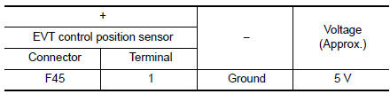
Is the inspection result normal? YES >> GO TO 3.
NO >> GO TO 2.
2.CHECK SENSOR POWER SUPPLY 2 CIRCUIT
Perform EC-484, "Diagnosis Procedure".
Is inspection result normal? YES >> Perform the trouble diagnosis for power supply circuit.
NO >> Repair or replace error-detected parts.
3.CHECK EVT CONTROL POSITION SENSOR GROUND CIRCUIT
- Turn ignition switch OFF.
- Disconnect ECM harness connector.
- Check the continuity between EVT control position sensor harness connector and ECM harness connector.
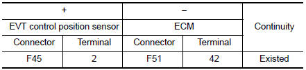
- Also check harness for short to power.
Is the inspection result normal? YES >> GO TO 4.
NO >> Repair or replace error-detected parts.
4.CHECK EVT CONTROL POSITION SENSOR INPUT SIGNAL CIRCUIT
- Disconnect ECM harness connector.
- Check the continuity between EVT control position sensor harness connector and ECM harness connector.
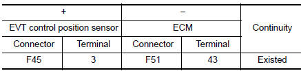
- Also check harness for short to ground and to power.
Is the inspection result normal? YES >> GO TO 5.
NO >> Repair or replace error-detected parts.
5.CHECK EVT CONTROL POSITION SENSOR
Check the EVT control position sensor. Refer to EC-387, "Component Inspection".
Is the inspection result normal? YES >> GO TO 6.
NO >> Replace EVT control position sensor. Refer to EM-64, "Exploded View".
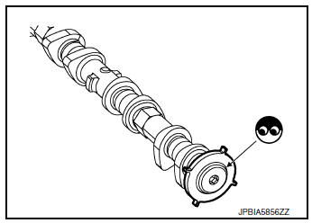
6.CHECK CAMSHAFT (EXT)
Check the following.
- Accumulation of debris to the signal plate of camshaft rear end
- Chipping signal plate of camshaft rear end
Is the inspection result normal? YES >> GO TO 7.
NO >> Remove debris and clean the signal plate of camshaft rear end or replace camshaft. Refer to EM-64, "Removal and Installation".
7.CHECK INTERMITTENT INCIDENT
Refer to GI-41, "Intermittent Incident".
>> INSPECTION END
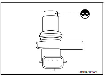
Component Inspection
1.EXHAUST VALVE TIMING (EVT) CONTROL POSITION SENSOR-1
- Turn ignition switch OFF.
- Disconnect EVT control position sensor harness connector.
- Loosen the fixing bolt of the sensor.
- Remove the sensor.
- Visually check the sensor for chipping.
Is the inspection result normal? YES >> GO TO 2.
NO >> Replace EVT control position sensor. Refer to EM-64, "Exploded View".
2.EVT CONTROL POSITION SENSOR-2
Check resistance EVT control position sensor terminals as shown below.
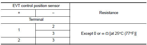
Is the inspection result normal? YES >> INSPECTION END
NO >> Replace EVT control position sensor. Refer to EM-64, "Exploded View".
 P0850 PNP switch
Description
Transmission range switch is turn ON when the selector lever is P or N.
ECM detects the position because the continuity of the line (the ON) exists.
DTC Description
DTC DETECTION LOG ...
 P1148 closed loop control
DTC Description
DTC DETECTION LOGIC
DTC No.
CONSULT screen terms
(Trouble diagnosis content)
DTC detecting condition
P1148
CLOSED LOOP-B1
(CLOSED LOOP-B1)
The close ...
Other materials:
ECU diagnosis information
CAN GATEWAY
Reference Value
VALUES ON THE DIAGNOSIS TOOL
NOTE:
The following table includes information (items) inapplicable to this vehicle.
For information (items) applicable
to this vehicle, refer to CONSULT display items.
DTC Index
...
Auto operation does not operate but manual operate normally
(driver side)
Diagnosis Procedure
1.PERFORM INITIALIZATION PROCEDURE
Initialization procedure is executed and operation is confirmed.
Refer to PWC-27, "ADDITIONAL SERVICE WHEN REMOVING BATTERY NEGATIVE TERMINAL :
Special
Repair Requirement".
Is the inspection result normal?
YES >> Insp ...
Preparation
Special Service Tool
The actual shape of the tools may differ from those illustrated here.
Tool number
(TechMate No.)
Tool name
Description
KV40107300
( — )
Boot band crimping tool
Installing boot band
KV40107500
( — )
Drive shaft attach ...
