Nissan Rogue Service Manual: Power switch illumination circuit
Description
Provides the power supply and the ground to control the power switch illumination.
Component Function Check
1.CHECK POWER SWITCH ILLUMINATION OPERATION
 CONSULT ACTIVE TEST
- Turn the power switch ON.
- Select “ENGINE SW ILLUMI” of “BCM” active test item.
- With operating the test items, check that the power switch illumination turns ON/OFF.
On : Power switch illumination ON
Off : Power switch illumination OFF
Does the power switch illumination turn ON/OFF? YES >> Power switch illumination circuit is normal.
NO >> Refer to INL-52, "Diagnosis Procedure".
Diagnosis Procedure
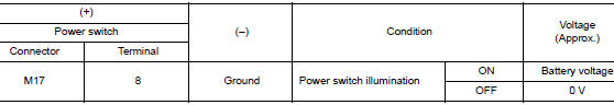
1.CHECK POWER SWITCH ILLUMINATION POWER SUPPLY OUTPUT
- Turn power switch OFF.
- Disconnect power switch connector.
- Check voltage between power switch harness connector and ground.
Is the inspection result normal? YES >> GO TO 4.
NO >> GO TO 2.
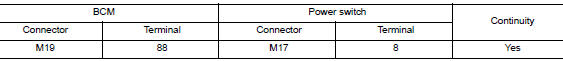
2.CHECK POWER SWITCH ILLUMINATION POWER SUPPLY OPEN CIRCUIT
- Turn the power switch OFF.
- Disconnect BCM connector.
- Check continuity between BCM harness connector and the power switch harness connector.
Is the inspection result normal? YES >> GO TO 3.
NO >> Repair or replace harnesses.
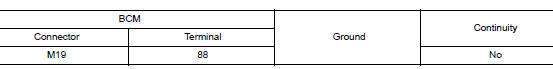
3.CHECK POWER SWITCH ILLUMINATION POWER SUPPLY SHORT CIRCUIT
Check continuity between BCM harness connector and ground.
Is the inspection result normal? YES >> Replace BCM. Refer to BCS-75, "Removal and Installation" (with intelligent Key system) or BCS- 135, "Removal and Installation" (without Intelligent Key system).
NO >> Repair or replace harnesses.
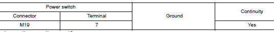
4.CHECK POWER SWITCH ILLUMINATION GROUND CIRCUIT
- Turn the power switch OFF.
- Check continuity between power switch harness connector and ground.
Is the inspection result normal? YES >> Replace power switch. Refer to SEC-112, "Removal and Installation".
NO >> Repair or replace harnesses.
 Luggage room lamp circuit
Description
Controls the luggage room lamp (ground side) to turn the luggage room lamp ON
and OFF.
Diagnosis Procedure
CAUTION:
Before performing the diagnosis, check that the following is norma ...
 Symptom diagnosis
INTERIOR LIGHTING SYSTEM SYMPTOMS
Symptom Table
CAUTION:
Perform the self-diagnosis with CONSULT before the symptom diagnosis. Perform
the trouble diagnosis
if any DTC is detected.
S ...
Other materials:
Heated seats (if so equipped)
The front seats are warmed by built-in heaters.
Start the engine.
Push the LO or HI position of the switch, as
desired. The indicator light in the switch will
illuminate.
The heater is controlled by a thermostat,
automatically turning the heater on and off.
The in ...
Low tire pressure warning lamp blinks
Description
The low tire pressure warning lamp blinks when the power switch is turned ON.
NOTE:
The position of an inactive tire pressure sensor can be identified by checking
the blinking timing of the low tire
pressure warning lamp.
Diagnosis Procedure
1.TIRE PRESSURE SENSOR ID REGISTRA ...
P0182, P0183 FTT sensor
DTC Description
DTC DETECTION LOGIC
DTC No.
CONSULT screen terms
(Trouble diagnosis content)
DTC detecting condition
P0182
FTT SEN/CIRCUIT
(Fuel temperature sensor ″A″ circuit low)
An excessively low voltage from the sensor is sent to ECM.
P01 ...
