Nissan Rogue Service Manual: System
INTERIOR ROOM LAMP CONTROL SYSTEM
INTERIOR ROOM LAMP CONTROL SYSTEM : System Description
SYSTEM DIAGRAM
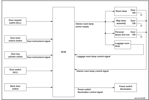
OUTLINE
- Interior room lamps* are controlled by interior room lamp timer control
function of BCM.
*: Map lamp and room lamp (when map lamp switch and room lamp switch are in DOOR position).
- Luggage room lamp is controlled by luggage room lamp control function of BCM.
- Power switch illumination is controlled by the power switch illumination control function of BCM.
INTERIOR ROOM LAMP TIMER CONTROL
Interior Room Lamp Timer Basic Operation
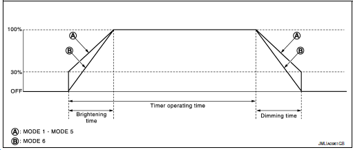
NOTE: A: Sets the interior room lamp gradual brightening and dimming time.
B: Gradually dims from 100% to 0% and gradually brightens 0% to 100% in 1 second.
- The interior room lamp turns ON and OFF (gradual brightening and dimming) by the interior room lamp timer.
- BCM judges the vehicle condition with the following items. It activates the interior room timer.
- Power switch status
- Door switch signal
- Door lock/unlock signal (Remote keyless entry receiver, each door request switch, door lock/unlock switch, door key cylinder switch)
NOTE: Each function of interior room lamp timer can be set by CONSULT. Refer to BCS-18, "INT LAMP : CONSULT Function (BCM - INT LAMP)" (with Intelligent Key system) or BCS-89, "INT LAMP : CONSULT Function (BCM - INT LAMP)" (without Intelligent Key system).
Interior Room Lamp ON Operation:
- BCM always turns the interior room lamp ON when any door opens.
- BCM activates the interior room lamp timer in any of the following conditions to turn the interior room lamp ON for a period of time:
- Status of all doors changes from open to close
- Power switch is turned ON → OFF
- Door unlock signal is detected when all doors close
NOTE: The timer restarts if new condition is input during the timer operating time.
Interior Room Lamp OFF Operation: BCM stops the timer in any of the following conditions to turn the interior room lamp OFF.
- The timer operating time is expired
- Power switch is turned OFF → ON
- Door lock signal is detected with all doors close except back door.
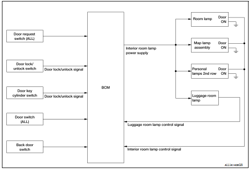
LUGGAGE ROOM LAMP CONTROL
BCM turns luggage room lamp ON when the following condition is detected:
- Back door switch is ON
BCM turns luggage room lamp OFF when the following condition is detected:
- Back door switch is OFF
POWER SWITCH ILLUMINATION CONTROL
Power Switch Illumination Basic Operation: BCM provides the power supply to turn the power switch illumination ON.
Power Switch Illumination ON Operation BCM turns the power switch illumination ON in the following conditions.
- Power switch ON
- Any of the following conditions with power switch OFF:
- Driver side door is LOCK → UNLOCK
- Driver side door is open
Power Switch Illumination OFF Operation
BCM turns the power switch illumination OFF in any of the following conditions:
- The push-button power switch illumination ON conditions are not satisfied.
- Any of the following conditions with power switch OFF:
- The power switch illumination ON conditions do not change (15 seconds after the power switch OFF)
- Driver side door is UNLOCK → LOCK
INTERIOR ROOM LAMP BATTERY SAVER SYSTEM
INTERIOR ROOM LAMP BATTERY SAVER SYSTEM : System Description
SYSTEM DIAGRAM
OUTLINE
- Interior room lamp battery saver is controlled by BCM.
- BCM turns applicable lamps OFF depending on the vehicle condition. This function prevents the 12V battery from over-discharging if the driver neglects turning OFF the lamps.
Applicable lamps:
- Map lamp
- Room lamp
- Luggage room lamp
- Personal lamps 2nd row (if equipped)
INTERIOR ROOM LAMP BATTERY SAVER FUNCTION
- When the power switch is turned to other position than ON, BCM operates the timer for a period of time to cut the interior room lamp power supply.
- BCM restarts the timer when any of the following signals changes while operating the timer:
- Power switch status
- Door switch signal (ALL)
- Door lock/unlock signal (remote keyless entry receiver, each door request switch, door lock and unlock switch, door key cylinder switch)
- BCM provides the interior room lamp power supply continuously when the power switch position is ON.
NOTE: Each function of interior room lamp battery saver can be set by CONSULT. Refer to BCS-18, "INT LAMP : CONSULT Function (BCM - INT LAMP)" (with itelligent Key system) or BCS-89, "INT LAMP : CONSULT Function (BCM - INT LAMP)" (without Intelligent Key system).
ILLUMINATION CONTROL SYSTEM
ILLUMINATION CONTROL SYSTEM : System Description
SYSTEM DIAGRAM
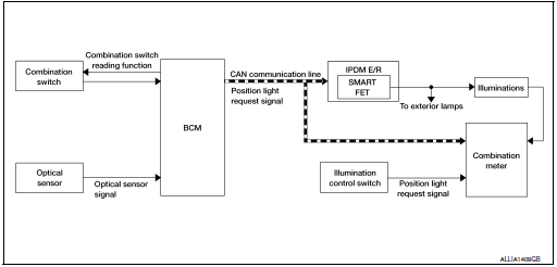
OUTLINE
Each illumination lamp is controlled by each function of BCM and IPDM E/R.
Controlled by BCM:
- Combination switch reading function
- Headlamp control function
Controlled by IPDM E/R:
- Smart FET control function
Controlled by combination meter:
- Meter illumination control function
ILLUMINATION CONTROL
- BCM detects the combination switch condition by the combination switch reading function.
- BCM transmits position light request signal to IPDM E/R and combination meter according to tail lamp ON condition.
Tail lamp ON condition:
- Lighting switch 1ST
- Lighting switch 2ND
- Lighting switch AUTO, and the auto light function ON judgment
- Lighting switch AUTO, with the front fog lamp switch ON and the power switch ON
- IPDM E/R turns each illumination lamp ON according to position light request signal. It provides the power supply to each illumination lamp.
- Combination meter enters in the nighttime mode according to position light request signal. Under the nighttime mode the combination meter controls the illuminance by controlling the each illumination lamp.
AUTO LIGHT ADJUSTMENT SYSTEM
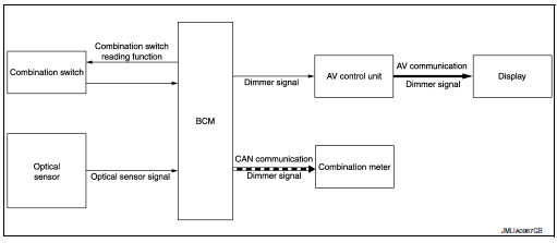
AUTO LIGHT ADJUSTMENT SYSTEM : System Description
SYSTEM DIAGRAM
OUTLINE
Auto light adjustment system is controlled by each function of BCM, combination meter and AV control unit
Controlled by BCM:
- Auto light system
- Auto light adjustment system
AUTO LIGHT ADJUSTMENT SYSTEM
Description
- BCM supplies voltage to the optical sensor when the power switch is turned ON.
- Optical sensor converts outside brightness (lux) to voltage and transmits the optical sensor signal to BCM.
- BCM judges dimming/brightening of combination meter and display according to brightness outside the vehicle, when power switch is ON.
- BCM transmits dimmer signal to combination meter via CAN communication, according to auto light adjustment conditions. Dimmer signal is also transmitted to AV control unit.
NOTE: As to dimming/brightening timing, the sensitivity depends on settings. The settings can be changed with CONSULT.
Refer to BCS-19, "HEADLAMP : CONSULT Function (BCM - HEADLAMP)" (with Intelligent Key system) or BCS-90, "HEADLAMP : CONSULT Function (BCM - HEADLAMP)" (without Intelligent Key system).
 Component parts
Component Parts Location
Rear luggage area (RH)
Front headliner area
Engine compartment (LH)
Left side of instrument panel (view
with finish panel removed)
Instrument p ...
 Diagnosis system (BCM) (with intelligent key system)
COMMON ITEM
COMMON ITEM : CONSULT Function (BCM - COMMON ITEM)
APPLICATION ITEM
CONSULT performs the following functions via CAN communication with BCM.
Direct Diagnostic Mode
De ...
Other materials:
Wheel sensor
FRONT WHEEL SENSOR
FRONT WHEEL SENSOR : Exploded View
Front LH wheel sensor
Harness connector
Slant line
FRONT WHEEL SENSOR : Removal and Installation
CAUTION:
Be careful not to damage front wheel sensor edge and sensor
rotor teeth.
When removing the front ...
Radiator
Exploded View
REMOVAL
Reservoir tank
Reservoir tank cap
Reservoir tank hose
Mounting rubber (upper)
Radiator cap
Radiator
CVT fluid cooler hose
Clamp
CVT fluid cooler hose
Mounting rubber (lower)
O-ring
Drain plug
...
FM/AM/SAT radio with compact disc (CD) player (Type B) (if so equipped)
FM/AM/SAT radio with compact disc (CD) player (Type B)
FM-AM button
CD eject button
CD insert slot
Backward seek button
button
Forward seek button
BACK button
TUNE/SCROLL knob, ENTER/AUDIO button
Display screen
POWER but ...
