Nissan Rogue Service Manual: Component parts
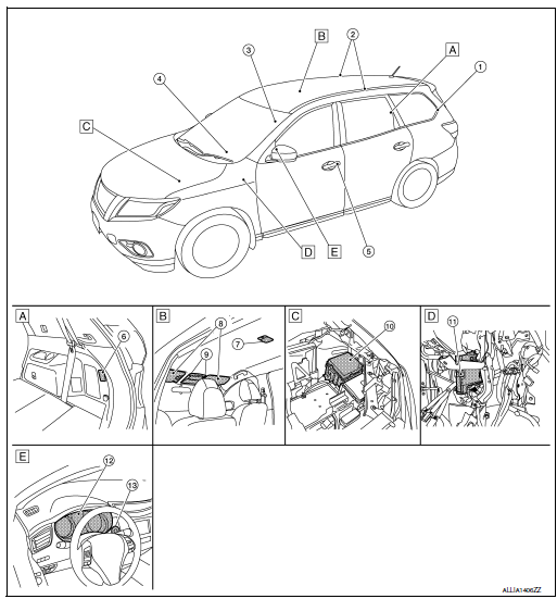
Component Parts Location

- Rear luggage area (RH)
- Front headliner area
- Engine compartment (LH)
- Left side of instrument panel (view with finish panel removed)
- Instrument panel (LH)
|
No. |
Part |
Description |
| 1 | Back door lock assembly (back door switch) | Refer to DLK-21, "Back Door Lock Assembly". |
| 2 | Personal lamps 2nd row | Refer to INL-63, "Bulb Specifications". |
| 3 | Front door request switch (RH) | Refer to DLK-24, "Front Door Request Switch (RH)". |
| 4 | Optical sensor | Refer to EXL-10, "Optical Sensor". |
| 5 | Front door request switch (LH) | Refer to DLK-24, "Front Door Request Switch (LH)". |
| 6 | Luggage room lamp | Refer to INL-63, "Bulb Specifications". |
| 7 | Room lamp | Refer to INL-63, "Bulb Specifications". |
| 8 | Vanity mirror lamps | Refer to INL-63, "Bulb Specifications". |
| 9 | Map lamp assembly | Refer to INL-63, "Bulb Specifications". |
| 10 | IPDM E/R | Controls audio unit and AV control unit illumination supply voltage according to the request signal from BCM (via CAN communication). Refer to PCS-4, "Component Parts Location" for detailed installation location. |
| 11 | BCM |
Refer to BCS-7, "BODY CONTROL SYSTEM : Component Parts Location" (with Intelligent Key system) or BCS-79, "BODY CONTROL SYSTEM : Component Parts Location" (without Intelligent Key system) for detailed installation location. |
 System
INTERIOR ROOM LAMP CONTROL SYSTEM
INTERIOR ROOM LAMP CONTROL SYSTEM : System Description
SYSTEM DIAGRAM
OUTLINE
Interior room lamps* are controlled by interior room lamp timer control
...
Other materials:
Radio
With the ignition placed in the ACC or ON position,
press the or POWER
button/VOLUME control knob to turn the radio
on. If you listen to the radio with the engine not
running, the ignition should be placed in the ACC
position.
Radio reception is affected by station signal
strength, distance ...
P2127, P2128 APP sensor
DTC Description
DTC DETECTION LOGIC
DTC No.
CONSULT screen terms
(Trouble diagnosis content)
DTC detecting condition
P2127
APP SEN 2/CIRC
(Throttle/pedal position sensor/switch ″E″
circuit low)
An excessively low voltage from the APP sensor 2 is sen ...
B1431 seat belt pre-tensioner
DTC Logic
DTC DETECTION LOGIC
CONSULT name
DTC
DTC detecting condition
Repair order
FRONT PRE-TEN RH CIRCUIT
[OPEN]
B1431
RH seat belt pre-tensioner circuit is open.
Refer to SRC-61, "Diagnosis Procedure"
FRONT PRE-TEN RH CIRC ...

