Nissan Rogue Service Manual: Wheel sensor
FRONT WHEEL SENSOR
FRONT WHEEL SENSOR : Exploded View
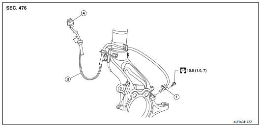
- Front LH wheel sensor
- Harness connector
- Slant line
FRONT WHEEL SENSOR : Removal and Installation
CAUTION:
- Be careful not to damage front wheel sensor edge and sensor rotor teeth.
- When removing the front wheel hub and bearing, first remove the front wheel sensor from the steering knuckle. Failure to do so may result in damage to the front wheel sensor wires making the front wheel sensor inoperative.
- Pull out the front wheel sensor, being careful to turn it as little as possible. Do not pull on the front wheel sensor harness.
- Before installation, check if foreign objects such as iron fragments are adhered to the pick-up part of the front wheel sensor or to the inside of the hole in the steering knuckle for the front wheel sensor, or if a foreign object is caught in the surface of the sensor rotor. Fix as necessary and then install the front wheel sensor.
REMOVAL
- Remove the front wheel and tire using power tool. Refer to WT-57, "Adjustment".
- Partially remove the fender protector to gain access to the wheel sensor harness connector. Refer to EXT- 28, "FENDER PROTECTOR : Exploded View".
- Disconnect the harness connector from the front wheel sensor.
- Remove the front wheel sensor bolt from the wheel hub and bearing.
- Remove the front wheel sensor from the strut bracket.
- Remove the front wheel sensor from the steering knuckle.
INSTALLATION
Installation is in the reverse order of removal.
CAUTION:
- When installing, make sure there is no foreign material such as iron chips on and in the hole in the steering knuckle for the front wheel sensor. Make sure no foreign material has been caught in the sensor rotor. Remove any foreign material and clean the mount.
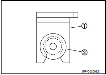
- Do not twist front wheel sensor harness when installing front wheel sensor. Check that grommet (2) is fully inserted to bracket (1). Check that front wheel sensor harness is not twisted after installation.
REAR WHEEL SENSOR
REAR WHEEL SENSOR : Exploded View
FWD
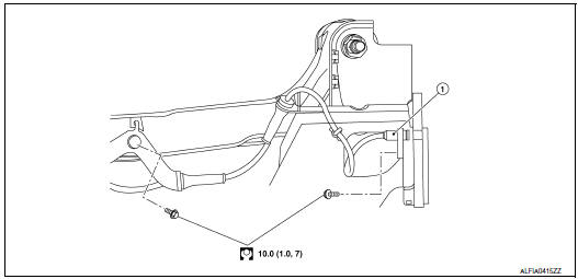
- Rear LH wheel sensor
AWD

- Rear LH wheel sensor
REAR WHEEL SENSOR : Removal and Installation
CAUTION:
- Be careful not to damage rear wheel sensor edge and sensor rotor teeth.
- When removing the rear wheel hub and bearing, first remove the rear wheel sensor from the rear wheel hub and bearing (FWD) or the rear axle housing (AWD). Failure to do so may result in damage to the rear wheel sensor making the rear wheel sensor inoperative.
- Pull out the rear wheel sensor, being careful to turn it as little as possible. Do not pull on the rear wheel sensor harness.
- Before installation, check if foreign objects such as iron fragments are adhered to the pick-up part of the rear wheel sensor or to the inside of the hole in the rear wheel hub and bearing (FWD) or the rear axle housing (AWD) for the rear wheel sensor, or if a foreign object is caught in the surface of the sensor rotor. Fix as necessary and then install the rear wheel sensor.
REMOVAL
- Remove the rear wheel and tire using power tool. Refer to WT-57, "Adjustment".
- Remove the rear wheel sensor bolt.
- Disconnect the harness connector from the rear wheel sensor.
- Remove the rear wheel sensor from the wheel hub and bearing (FWD) or the rear axle housing (AWD).
- Remove the rear wheel sensor harness grommet from the bracket.
- Remove the bolt, the rear wheel sensor harness, and the rear wheel sensor from the bracket.
INSTALLATION
Installation is in the reverse order of removal.
CAUTION:
- When installing, make sure there is no foreign material such as iron chips on and in the hole in the rear wheel hub and bearing (FWD) or the rear axle housing (AWD) for the rear wheel sensor. Make sure no foreign material has been caught in the sensor rotor. Remove any foreign material and clean the mount.
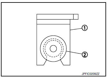
- Do not twist rear wheel sensor harness when installing rear wheel sensor. Check that grommet (2) is fully inserted to bracket (1). Check that rear wheel sensor harness is not twisted after installation.

 Sensor rotor
FRONT SENSOR ROTOR
FRONT SENSOR ROTOR : Removal and Installation - Front Sensor Rotor
The front wheel sensor rotor is an integral part of the wheel hub and bearing
and cannot be disassembled.
R ...
Other materials:
CAN system (type 4)
MAIN LINE BETWEEN IPDM-E AND DLC CIRCUIT
Diagnosis Procedure
1.CHECK CONNECTOR
Turn the ignition switch OFF.
Disconnect the battery cable from the negative terminal.
Check the following terminals and connectors for damage, bend and
loose connection (connector side
an ...
Anti-pinch system does not operate normally (driver side)
Diagnosis Procedure
1.PERFORM INITIALIZATION PROCEDURE
Initialization procedure is executed and operation is confirmed.
Refer to PWC-27, "ADDITIONAL SERVICE WHEN REMOVING BATTERY NEGATIVE TERMINAL :
Special
Repair Requirement".
Is the inspection result normal?
YES >> Insp ...
Throttle valve closed position learning
Description
Throttle Valve Closed Position Learning is a function of ECM to learn the
fully closed position of the throttle
valve by monitoring the throttle position sensor output signal. It must be
performed each time the harness connector
of the electric throttle control actuator or ECM is ...
