Nissan Rogue Service Manual: Interior room lamp power supply circuit
Description
Provides the interior room lamp power supply. Also cuts the power supply when the interior room lamp battery saver is activating.
Component Function Check
1.CHECK INTERIOR ROOM LAMP POWER SUPPLY FUNCTION
CONSULT ACTIVE TEST
- Turn power switch ON.
- Turn each interior room lamp ON.
- Map lamp
- Room lamp
- Personal lamps 2nd row (if equipped)
- Luggage room lamp
- Select ÔÇťBATTERY SAVERÔÇŁ of ÔÇťBCMÔÇŁ active test item.
- With operating the test items, check that each interior room lamp turns ON/OFF.
Off : Interior room lamp OFF
On : Interior room lamp ON
Does each interior room lamp turn ON/OFF? YES >> Interior room lamp power supply circuit is normal.
NO >> Refer to INL-46, "Diagnosis Procedure".
Diagnosis Procedure
1.CHECK INTERIOR ROOM LAMP POWER SUPPLY OUTPUT
 CONSULT ACTIVE TEST
- Turn power switch OFF.
- Turn power switch ON.
- Select ÔÇťBATTERY SAVERÔÇŁ of ÔÇťÔÇŁ active test item.
- With operating the test item, check continuity between BCM harness connector and ground.
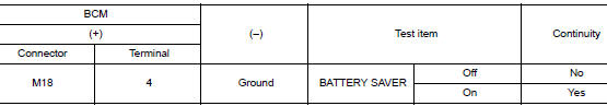
Is the inspection result normal? YES >> GO TO 2.
NO >> Replace BCM. Refer to BCS-75, "Removal and Installation" (with Intelligent Key system) or BCS- 135, "Removal and Installation" (without Intelligent Key system).
2.CHECK INTERIOR ROOM LAMP RELAY SIGNAL OPEN CIRCUIT
- Turn power switch OFF.
- Disconnect the BCM connector and room lamp relay.
- Check continuity between BCM harness connector and room lamp relay harness connector.
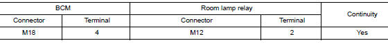
Is the inspection result normal? YES >> GO TO 3.
NO >> Repair or replace harnesses.
3.CHECK INTERIOR ROOM LAMP RELAY POWER SUPPLY CIRCUIT
- Check voltage at room lamp relay harness connector.
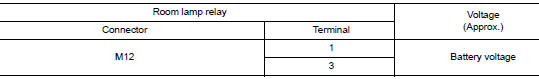
Is the inspection result normal? YES >> GO TO 4.
NO >> Repair or replace harnesses.
4.CHECK INTERIOR ROOM LAMP RELAY POWER SUPPLY OUTPUT
- Reconnect room lamp relay.
- Check voltage at room lamp relay harness connector.
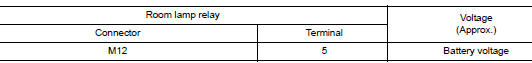
Is the inspection result normal? YES >> GO TO 5.
NO >> Replace room lamp relay.
5.CHECK INTERIOR ROOM LAMP RELAY POWER SUPPLY OUTPUT
- Disconnect he following connectors:
- Room lamp relay M12
- Map lamp assembly R6
- Room lamp R15
- Personal lamps 2nd row R16 (if equipped)
- Vanity mirror lamp LH R14
- Vanity mirror lamp RH R10
- Luggage room lamp B118
- Check continuity between room lamp relay connector M12 and interior room lamp connector in question.
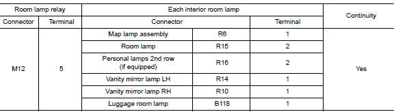
Is the inspection result normal? YES >> GO TO 6.
NO >> Repair or replace harnesses.
6.CHECK INTERIOR ROOM LAMP RELAY POWER SUPPLY OUTPUT SHORT CIRCUIT
Check continuity between room lamp relay and ground.
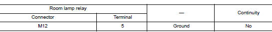
Is the inspection result normal? YES >> Check that each interior lamp has no internal short circuit.
NO >> Repair or replace harnesses.

 Interior room lamp control circuit
Description
Controls each interior room lamp (ground side) by PWM signal.
NOTE:
PWM signal control period is approximately 250 Hz (in the gradual
brightening/dimming).
Component Function Check
...
Other materials:
P0776 pressure control solenoid B
DTC Description
DTC DETECTION LOGIC
DTC
CONSULT screen terms
(Trouble diagnosis content
DTC detection condition
P0776
PC SOLENOID B
(Pressure Control Solenoid ÔÇťBÔÇŁ Performance/
Stuck Off)
When any of 1 or 2 is satisfied and this state is maintained for 10
...
Removal and installation
NATS ANTENNA AMP.
Removal and Installation
REMOVAL
Remove the steering column covers. Refer to IP-17, "Removal and
Installation".
Disconnect the harness connector from the NATS antenna amp.
Release pawls and remove NATS antenna amp. (1) from the
ignition sw ...
Power supply and ground circuit
WITH INTELLIGENT KEY SYSTEM
WITH INTELLIGENT KEY SYSTEM : Diagnosis Procedure
Regarding Wiring Diagram information, refer to BCS-50, "Wiring Diagram".
1. CHECK FUSE
Check that the following fuse is not blown.
Terminal No.
Signal name
Fuse No.
161
BCM power sup ...
