Nissan Rogue (T33) 2021-Present Service Manual: P0012 Intake Valve Timing Control
DTC Description
DTC DETECTION LOGIC
| DTC |
CONSULT screen terms (Trouble diagnosis content) | DTC detection condition | ||
|---|---|---|---|---|
| P0012 | 00 |
A camshaft position B1 (“A” Camshaft position - timing over-retarded bank 1) |
Diagnosis condition | Engine running |
| Signal (terminal) | — | |||
| Threshold | During the retarded control of intake valve timing control, the angle difference between actual angle and target angle is 13 degrees or more | |||
| Diagnosis delay time | 6 seconds | |||
POSSIBLE CAUSE A
-
Intake valve timing control actuator
-
Intake valve timing control motor
-
Camshaft sprocket (INT)
-
Wear or damage of the electric intake valve timing control actuator brush
-
Center target
POSSIBLE CAUSE B
-
Accumulation of debris to the signal plate of the camshaft
-
Timing chain installation
FAIL-SAFE
Engine Control System
| Fail safe mode | Nissan Ariya Vehicle behavior | |
|---|---|---|
| Device fix mode |
|
|
Stop/Start System
Not applicable
DTC CONFIRMATION PROCEDURE
PRECONDITIONING
If DTC Confirmation Procedure has been previously conducted, always perform the following procedure before conducting the next test.
-
Turn ignition switch OFF and wait at least 10 seconds.
-
Turn ignition switch ON.
-
Turn ignition switch OFF and wait at least 10 seconds.
TESTING CONDITION:
Before performing the following procedure, confirm that battery voltage is between 11 V and 16 V at idle.
>>
GO TO 2.
PERFORM DTC CONFIRMATION PROCEDURE-1
 With CONSULT
-
Turn ignition switch ON and select “DATA MONITOR” mode of “ENGINE” using CONSULT.
-
Start engine and warm it up to normal operating temperature.
-
Maintain the following conditions for at least 13 consecutive seconds. Hold the accelerator pedal as steady as possible.
ENG SPEED Less than 6,000 rpm Selector lever P or N position -
Stop Nissan Ariya vehicle with engine running and let engine idle for 13 seconds.
-
Check 1st trip DTC.
 With GST
Follow the procedure “With CONSULT” above.
Is 1st trip DTC detected?
YES>>Proceed to DTC Diagnosis Procedure.
NO>>GO TO 3.
PERFORM DTC CONFIRMATION PROCEDURE-2
With CONSULT
-
Select “DATA MONITOR” mode of “ENGINE” using CONSULT.
-
Maintain the following conditions for at least 20 consecutive seconds.
ENG SPEED Less than 6,000 rpm (A constant rotation is maintained.) Selector lever D position Driving location Driving Nissan Ariya vehicle uphill
(Increased engine load will help maintain the driving conditions required for this test.)CAUTION:
Always drive at a safe speed.
-
Check 1st trip DTC.
With GST
Follow the procedure “With CONSULT” above.
Is 1st trip DTC detected?
YES>>Proceed to DTC Diagnosis Procedure.
NO-1>>To check malfunction symptom before repair: Refer to Intermittent Incident.
NO-2>>Confirmation after repair: INSPECTION END
DTC Diagnosis Procedure
MALFUNCTION A
CAUTION:
Never reuse O-ring of electric intake valve timing control actuator. When replacing the electric intake valve timing control actuator, replace the O-ring.
CHECK ELECTRIC INTAKE VALVE TIMING CONTROL MOTOR CONTROL CIRCUIT
-
Turn ignition switch OFF.
-
Disconnect electric intake valve timing control motor harness connector.
-
Disconnect electric intake valve timing control module harness connector.
-
Check the continuity between the electric intake valve timing control motor harness connector and the electric intake valve timing control module harness connector.
Electric intake valve timing control motor Electric intake valve timing control module Continuity Connector Terminal Connector Terminal F91 1 F113 46 Existed 2 42 -
Also check harness for short to ground and short to power.
Is the inspection result normal?
YES>>GO TO 2.
NO>>Repair or replace error-detected parts.
CHECK ELECTRIC INTAKE VALVE TIMING CONTROL ACTUATOR BRUSH
-
Remove electric intake valve timing control actuator. Refer to Exploded View.
-
Check the state of brush for the electric intake valve timing control actuator.
Is the inspection result normal?
YES>>GO TO 3.
NO>>Replace the electric intake valve timing control actuator. Refer to Exploded View.
CHECK ELECTRIC INTAKE VALVE TIMING CONTROL ACTUATOR
-
Check the continuity between electric intake valve timing control actuator connector terminal and brush as following.
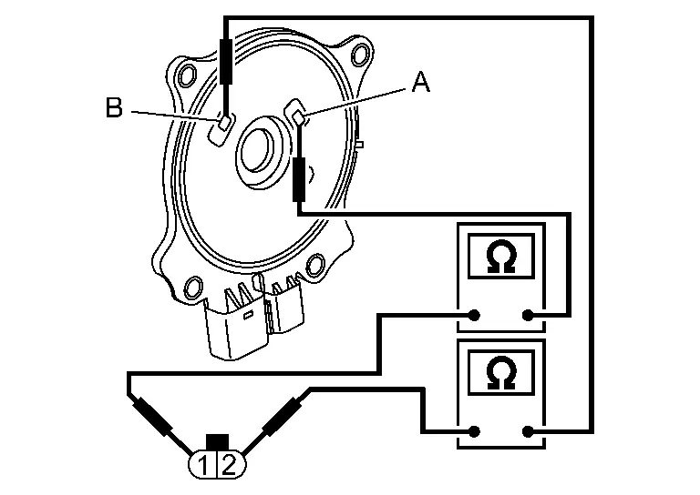
Electric intake valve timing control actuator Continuity Terminal Brush 1 A Existed B Not existed 2 B Existed A Not existed
Is the inspection result normal?
YES>>GO TO 4.
NO>>Replace the electric intake valve timing control actuator. Refer to Exploded View.
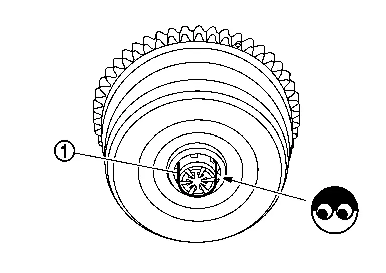
CHECK CENTER TARGET
Check the state of center target  .
.
Is the inspection result normal?
YES>>Replace camshaft sprocket (INT) (Electric intake valve timing motor is built-in). Refer to Exploded View.
NO>>Repair or replace the center target. Refer to Exploded View.
MALFUNCTION B
CHECK TIMING CHAIN INSTALLATION
Check service records for any recent repairs that may cause timing chain misalignment.
Are there any service records that may cause timing chain misalignment?
YES>>Check timing chain installation. Refer to Inspection.
NO>>GO TO 2.
CHECK CAMSHAFT SPROCKET AND TIMING CHAIN
Check the following.
-
Visually check for chipping camshaft
sprocket gear tooth.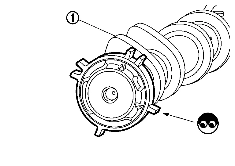
-
Timing chain tension and elongation.
Is the inspection result normal?
YES>>INSPECTION END
NO>>Repair or replace error-detected parts.
Other materials:
Steering Switch Signal B Circuit
Component Function Check
CHECK COMBINATION METER INPUT SIGNAL
CONSULT
Ignition switch ON.
Select “Steering switch input” in “Data monitor” mode of “M&A”.
Check that the function operates normally according to the following conditions:
Condition Value
CONTRO ...
U1cab-02 Intake Door Motor
DTC Description
DTC DETECTION LOGIC DTC No.
CONSULT screen terms
(Trouble diagnosis content) DTC detection condition
U1CAB-02
Intake door motor
(Intake door motor)
Diagnosis condition
Ignition switch ON
Signal (Terminal)
LIN (door motor) signal
Threshold
A/C amp. i ...
2wd. Preparation. Preparation
Preparation
Special Service Tool
Tool number
(TechMate No.)
Tool name Description
KV40104000
( – )
Hub lock nut wrench
a: 85 mm (3.35 in)
b: 65 mm (2.56 in)
Removing and Installing wheel hub lock nut.
KV40107300
( – )
Boot band crimping tool
Installing bo ...