Nissan Rogue (T33) 2021-Present Service Manual: U1cab-02 Intake Door Motor
DTC Description
DTC DETECTION LOGIC
| DTC No. |
CONSULT screen terms (Trouble diagnosis content) | DTC detection condition | |
|---|---|---|---|
| U1CAB-02 |
Intake door motor (Intake door motor) |
Diagnosis condition | Ignition switch ON |
| Signal (Terminal) | LIN (door motor) signal | ||
| Threshold | A/C amp. is not transmitting or receiving LIN communication with intake door motor | ||
| Diagnosis delay time | 2 second or more | ||
POSSIBLE CAUSE
-
Harness and connector (intake door motor circuit is open or shorted to ground)
-
Intake door motor
-
A/C amp.
FAIL-SAFE
ŌĆö
DTC CONFIRMATION PROCEDURE
PERFORM DTC CONFIRMATION PROCEDURE
 CONSULT
-
Start the engine.
-
Select ŌĆ£Self diagnosis resultŌĆØ mode of ŌĆ£HVACŌĆØ.
-
Check DTC.
Is DTC detected?
YES>>Refer to Diagnosis Procedure.
NO-1>>To check malfunction symptom before repair: Refer to Intermittent Incident.
NO-2>>Confirmation after repair: Inspection End.
DTC Diagnosis Procedure
CHECK INTAKE DOOR MOTOR POWER SUPPLY
-
Ignition switch ON.
-
Check voltage between intake door motor harness connector and A/C amp. harness connector.
| (+) | (ŌłÆ) | Voltage | ||
|---|---|---|---|---|
| Intake door motor | A/C amp. | |||
| Connector | Terminal | Connector | Terminal | |
| M147 | 1 | M55 | 58 | Battery voltage |
Is the inspection result normal?
YES>>GO TO 2.
NO>>GO TO 4.
CHECK INTAKE DOOR MOTOR GROUND CIRCUIT FOR OPEN
-
Ignition switch OFF.
-
Disconnect intake door motor connector and A/C amp. connector.
-
Check continuity between intake door motor harness connector and A/C amp. harness connector.
Intake door motor A/C amp. Continuity Connector Terminal Connector Terminal M147 2 M54 27 Yes
Is the inspection result normal?
YES>>GO TO 3.
NO>>Repair harness or connector.
CHECK INTAKE DOOR MOTOR LIN SIGNAL CIRCUIT
-
Connect intake door motor connector and A/C amp. connector.
-
Ignition switch ON.
-
Confirm output waveform between intake door motor harness connector and A/C amp. harness connector with oscilloscope.
(+) (ŌłÆ) Output waveform Intake door motor A/C amp. Connector Terminal Connector Terminal M147 3 M55 58 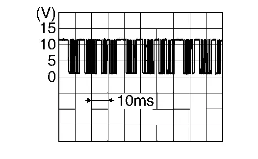
Is the inspection result normal?
YES>>Replace intake door motor. Refer to Removal and Installation.
NO>>GO TO 6.
CHECK INTAKE DOOR MOTOR POWER SUPPLY CIRCUIT FOR OPEN
-
Ignition switch OFF.
-
Disconnect intake door motor connector and A/C amp. connector.
-
Check continuity between intake door motor harness connector and A/C amp. harness connector.
Intake door motor A/C amp. Continuity Connector Terminal Connector Terminal M147 1 M54 1 Yes
Is the inspection result normal?
YES>>GO TO 5.
NO>>Repair harness or connector.
CHECK INTAKE DOOR MOTOR POWER SUPPLY CIRCUIT FOR SHORT
-
Disconnect following connectors.
-
Air mix door motor LH
-
Air mix door motor RH
-
Air mix door motor (rear)
-
Mode door motor
-
-
Check continuity between intake door motor harness connector and ground.
Intake door motor (ŌĆö) Continuity Connector Terminal M147 1 Ground No
Is the inspection result normal?
YES>>Replace A/C amp. Refer to Removal and Installation.
NO>>Repair harness or connector.
CHECK INTAKE DOOR MOTOR LIN SIGNAL CIRCUIT FOR OPEN
-
Ignition switch OFF.
-
Disconnect intake door motor connector and A/C amp. connector.
-
Check continuity between intake door motor harness connector and A/C amp. harness connector.
Intake door motor A/C amp. Continuity Connector Terminal Connector Terminal M147 3 M54 2 Yes
Is the inspection result normal?
YES>>GO TO 7.
NO>>Repair harness or connector.
CHECK INTAKE DOOR MOTOR LIN SIGNAL CIRCUIT FOR SHORT
-
Disconnect following connectors.
-
Air mix door motor LH
-
Air mix door motor RH
-
Air mix door motor (rear)
-
Mode door motor
-
-
Check continuity between intake door motor harness connector and ground.
Intake door motor (ŌĆö) Continuity Connector Terminal M147 3 Ground No
Is the inspection result normal?
YES>>Replace A/C amp. Refer to Removal and Installation.
NO>>Repair harness or connector.
Other materials:
U216e-87 Can Comm Circuit
DTC Description
CAN (Controller Area Network) is a serial communication system for
real time application. It is an on-Nissan Ariya vehicle multiplex
communication system with high data communication speed and excellent
error detectability. Many electronic control units are equipped onto
Nis ...
P2135 Tp Sensor
DTC Description
DTC DETECTION LOGICNOTE:
If DTC P2135 is displayed with DTC P06B0, first perform the trouble diagnosis for DTC P06B0. Refer to DTC Description.
DTC
CONSULT screen terms
(Trouble diagnosis content)
DTC detection condition
P2135
00
TP SENSOR-B1
(Throttle/Pedal ...
Removal and Installation. Tire Pressure Sensor
Exploded View
Screw
Tire pressure sensor
Valve
Valve core
Valve cap
: Comply with the assembly procedure when tightening. Refer to Removal and Installation.
: N┬Ęm (kg-m, in-lb)
: Always replace after every disassembly.
Removal & Install ...