Nissan Rogue (T33) 2021-Present Service Manual: Nissanconnect :: Removal and Installation
Av Control Unit
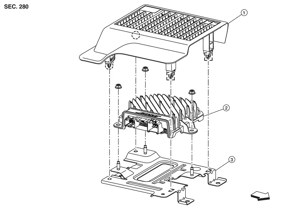
Exploded View
8-inch (21 cm) Display Without Maps
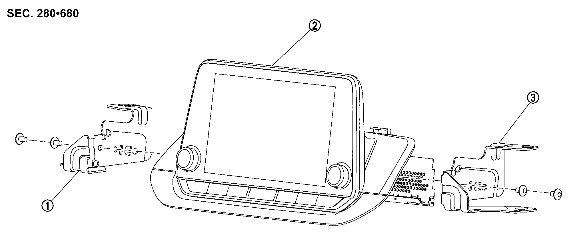
| 1. | Bracket LH | 2. | AV control unit | 3. | Bracket RH |
12.3-inch (31 cm) Display With Maps
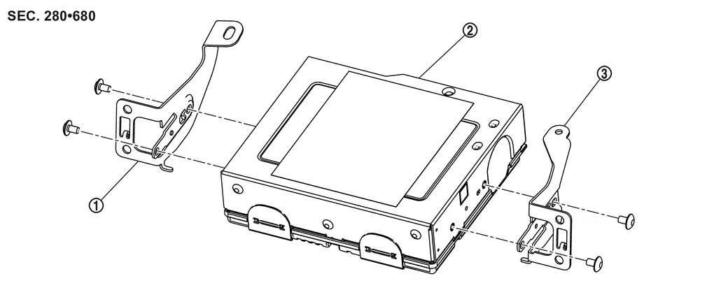
| 1. | Cluster lid | 2. | AV display unit | 3. | AV bracket |
| 1. | Bracket LH | 2. | AV control unit | 3. | Bracket RH |
Removal and Installation
CAUTION:
-
When removing interior trim, always use a remover tool that is made of plastic.
-
If replacing AV control unit, perform "ADDITIONAL SERVICE WHEN REPLACING AV CONTROL UNIT". Refer to Work Procedure.
REMOVAL
Disconnect the negative battery terminal. Refer to PRECAUTIONS FOR REMOVING BATTERY TERMINAL : Precautions.
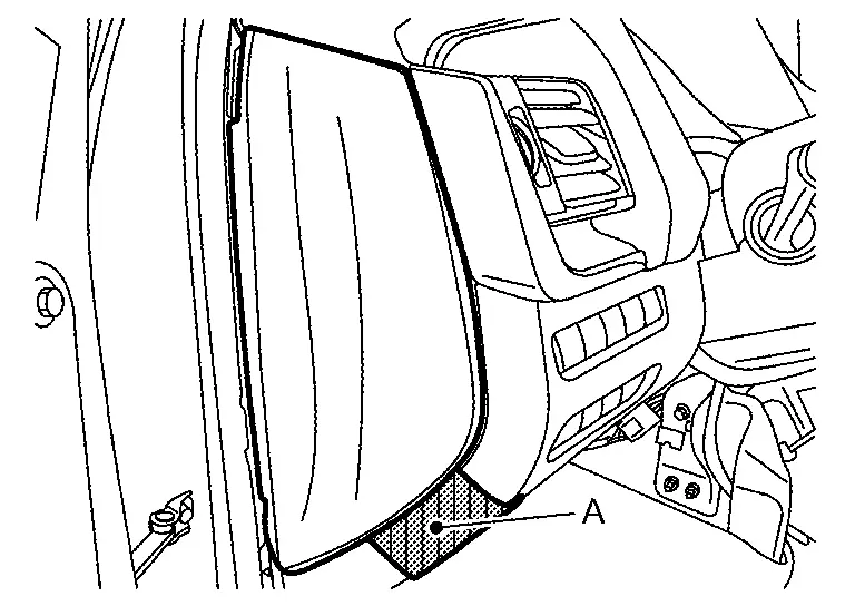
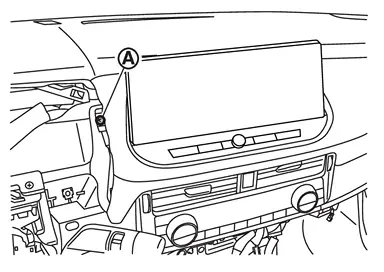
Remove instrument mask LH.Apply protective tape (A) on the part to protect it from damage.
 |
: Pawl |
Disengage upper fixing metal clips of instrument lower panel LH. Refer to Removal and Installation.
 NOTE:
NOTE:
When only removing the AV control unit, float the instrument lower panel LH to secure a space to remove the cluster lid A.
Disengage the upper driver side fixing metal clip of instrument lower panel center. Refer to Removal and Installation.
NOTE:
When only removing the AV control unit, float the instrument lower panel center to secure a space to remove the cluster lid A.
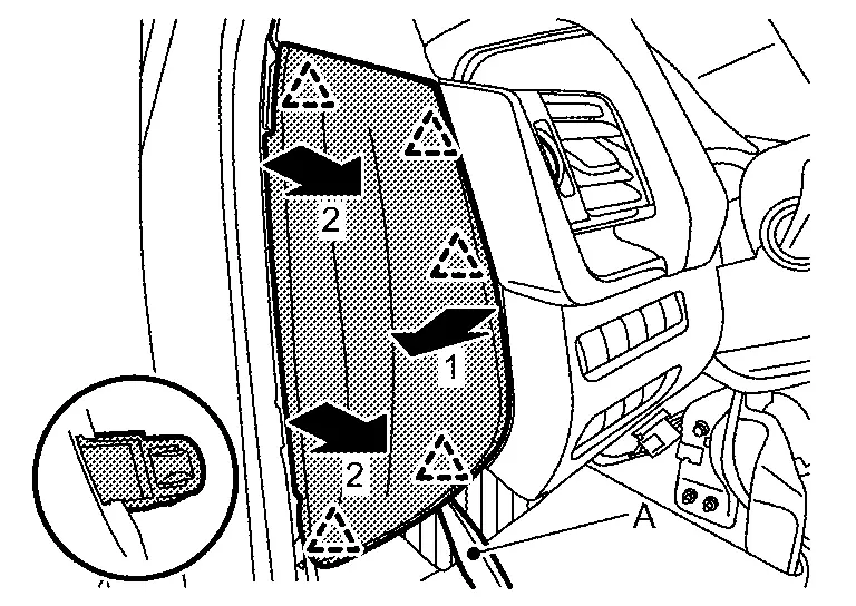
Disengage fixing pawls, and then remove skirt portion of cluster lid A.
|
: Pawl |
Disengage fixing pawls and metal clips according to numerical order 1→2 indicated by arrows as shown in the figure, and then remove cluster lid A.
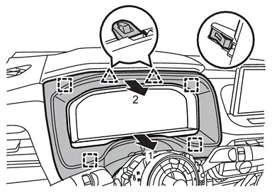
|
: Pawl |
 |
: Metal clip |
Remove instrument pad B.Remove fixing screw (A).
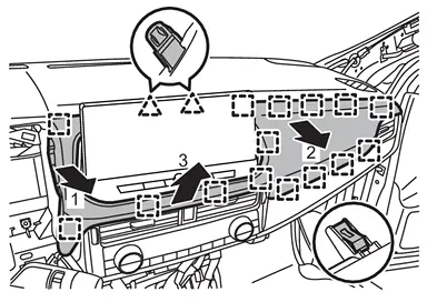
|
: Pawl |
|
: Metal clip |
CAUTION:
When removing instrument pad B, cover AV display unit surface with a shop cloth to prevent it from being damaged.
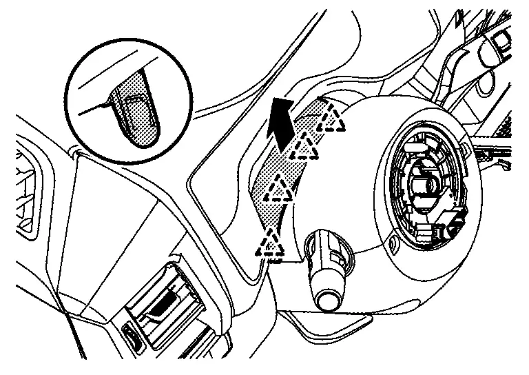
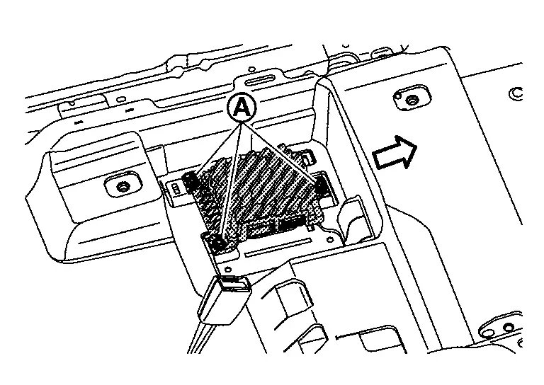
Remove the AV control unit.For 8-inch unit perform the following:
-
Remove 8-inch AV control unit mounting bolts (A).
-
Disconnect harness connectors, and then remove AV control unit assembly.
8-inch (21 cm) Display Without Maps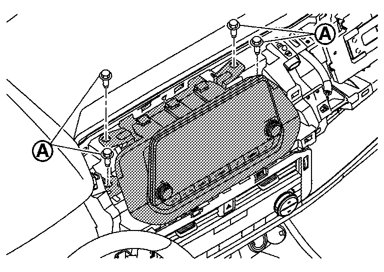
-
Remove 12.3-inch AV display unit mounting bolts (A).
-
Disconnect harness connectors, and then remove AV display unit assembly.
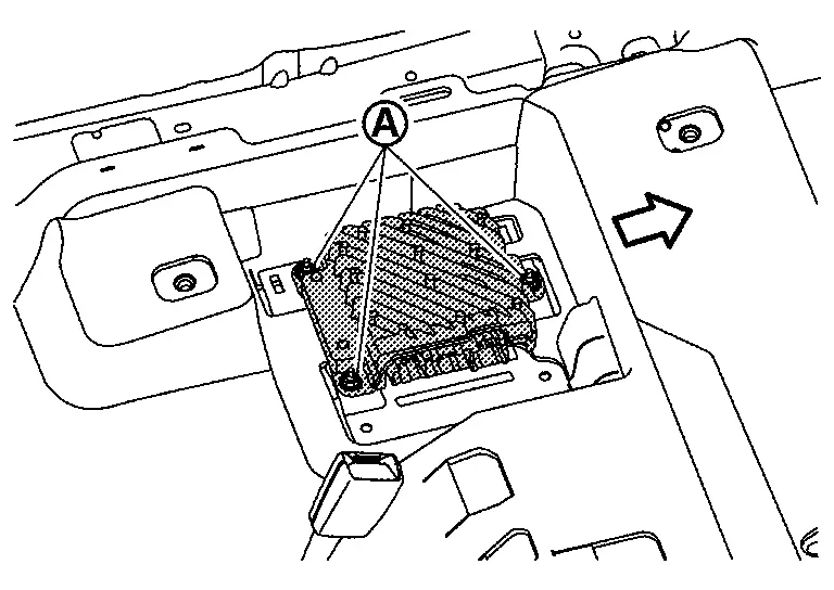
-
Remove 12.3-inch AV control unit mounting screws (A).
-
Disconnect harness connectors, and then remove AV control unit assembly.
12.3-inch (31cm) Display With Maps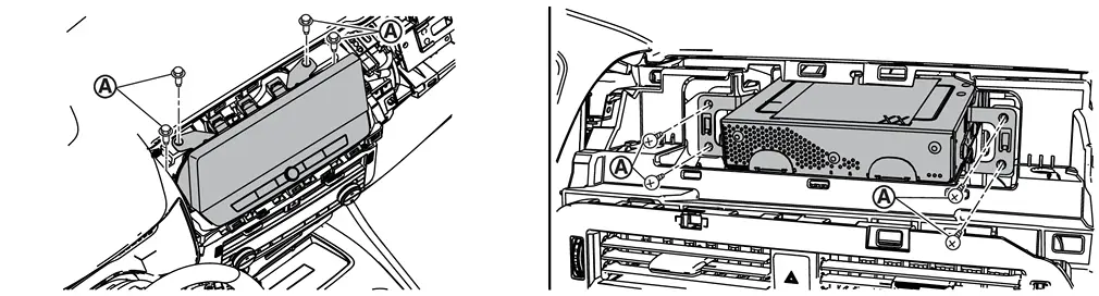
Remove the bracket mounting screws, and then remove the brackets from the AV control unit. Refer to Exploded View.
INSTALLATION
Installation is in the reverse order of removal.
CAUTION:
If replacing AV control unit, perform "ADDITIONAL SERVICE WHEN REPLACING AV CONTROL UNIT". Refer to Work Procedure.
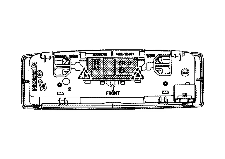
Active Noise Control Unit
Exploded View
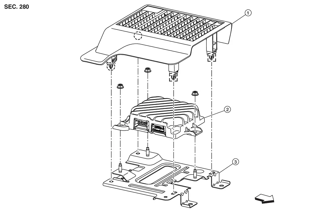
| 1. | Cover | 2. | Active noise control unit | 3. | Bracket |
|
: Metal clip |  |
: Clip | ||
 |
: Nissan Ariya Vehicle front | ||||
Removal and Installation
Removal
Remove the front seat (driver side). Refer to Removal and Installation.
Remove the cover.
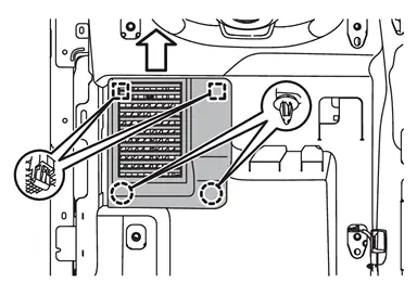
|
: Metal clip |
|
: Clip |
|
: Nissan Ariya Vehicle front |
Disconnect the harness connectors.
Remove the mounting nuts  ,and then remove the active noise control unit.
|
: Nissan Ariya Vehicle front |
INSTALLATION
Installation is in the reverse order of removal.
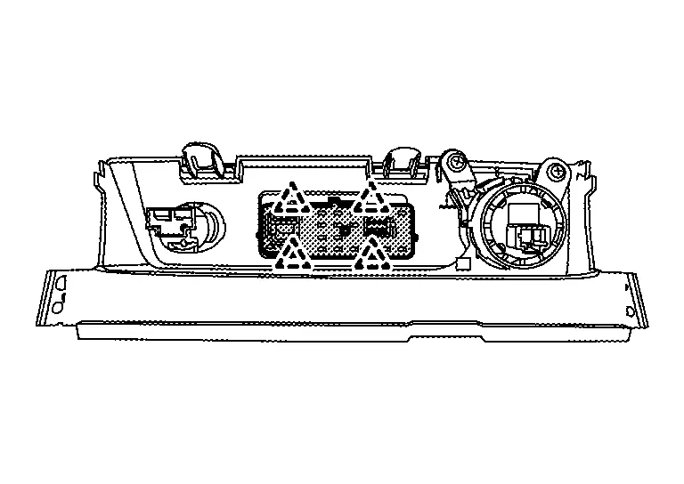
Bose Speaker Amp.
Exploded View
| 1. | Cover | 2. | BOSE speaker amp. | 3. | Bracket |
|
: Metal clip | |
: Clip | ||
|
: Nissan Ariya Vehicle front | ||||
Removal and Installation
CAUTION:
Be sure to perform "ADDITIONAL SERVICE WHEN REPLACING BOSE SPEAKER AMP." when replacing BOSE speaker amp. Or not doing so, BOSE speaker amp. control function does not operate normally. Refer to Work Procedure.
Removal
Remove the front seat (driver side). Refer to Removal and Installation.
Remove the cover.
|
: Metal clip |
|
: Clip |
|
: Nissan Ariya Vehicle front |
Disconnect the harness connectors.
Remove the mounting nuts ,and then remove the BOSE speaker amp.
|
: Nissan Ariya Vehicle front |
INSTALLATION
Installation is in the reverse order of removal.
CAUTION:
Be sure to perform the configuration must be performed when replacing BOSE speaker amp. Refer to Description.
Front Door Speaker
Without Bose and Active Noise Cancellation
Removal and Installation
REMOVAL
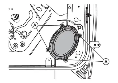
Remove the front door finisher. Refer to Removal and Installation.
Remove the front door speaker mounting bolts (A).
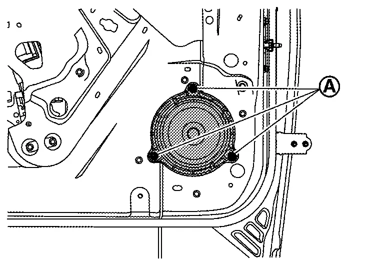
Disconnect the connector to remove the front door speaker.
INSTALLATION
Installation is in the reverse order of removal.
Without Bose with Active Noise Cancellation
Removal and Installation
REMOVAL
Remove the front door finisher. Refer to Removal and Installation.
Remove the front door speaker mounting bolts (A).
Disconnect the connector to remove the front door speaker.
INSTALLATION
Installation is in the reverse order of removal.
With Bose
Removal and Installation
REMOVAL
Remove the front door finisher. Refer to Removal and Installation.
Remove the front door speaker mounting bolts (A).
Disconnect the connector to remove the front door speaker.
INSTALLATION
Installation is in the reverse order of removal.
Front Speaker
Without Bose
Removal and Installation
REMOVAL
Remove the speaker grille. Refer to Removal and Installation.
Remove the instrument panel speaker mounting bolts (A).
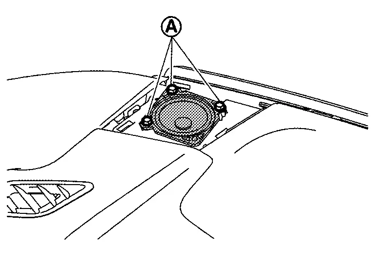
Disconnect the harness connector to remove the instrument panel speaker.
INSTALLATION
Installation is in the reverse order of removal.
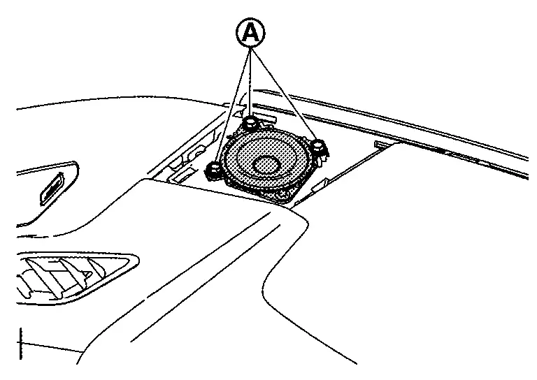
With Bose
Removal and Installation
REMOVAL
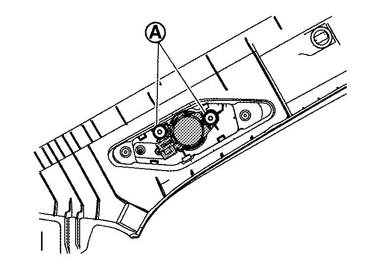
Remove the front pillar garnish. Refer to Removal and Installation.
Remove the screws (A) to remove the front speaker from the front pillar garnish.
INSTALLATION
Installation is the reverse order of removal.
Rear Door Speaker
Without Bose
Removal and Installation
REMOVAL
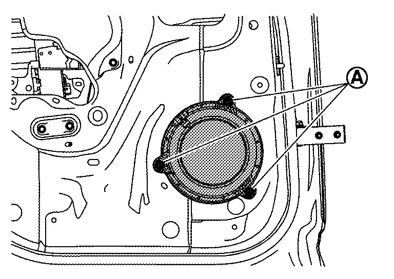
Remove the rear door finisher. Refer to Removal and Installation.
Remove the rear door speaker mounting bolts (A).

Disconnect the connector to remove the rear door speaker.
INSTALLATION
Installation is in the reverse order of removal.
With Bose
Removal and Installation
REMOVAL
Remove the rear door finisher. Refer to Removal and Installation.
Remove the rear door speaker mounting bolts (A).
Disconnect the connector to remove the rear door speaker.
INSTALLATION
Installation is in the reverse order of removal.
Instrument Panel Speaker
Removal and Installation
REMOVAL
Remove the speaker grille. Refer to Removal and Installation.
Remove the instrument panel speaker mounting bolts (A).
Disconnect the harness connector to remove the instrument panel speaker.
INSTALLATION
Installation is in the reverse order of removal.
Subwoofer
Removal and Installation
REMOVAL
Lift luggage floor board rear end and maintain it.
Remove the sub woofer clamp (A).
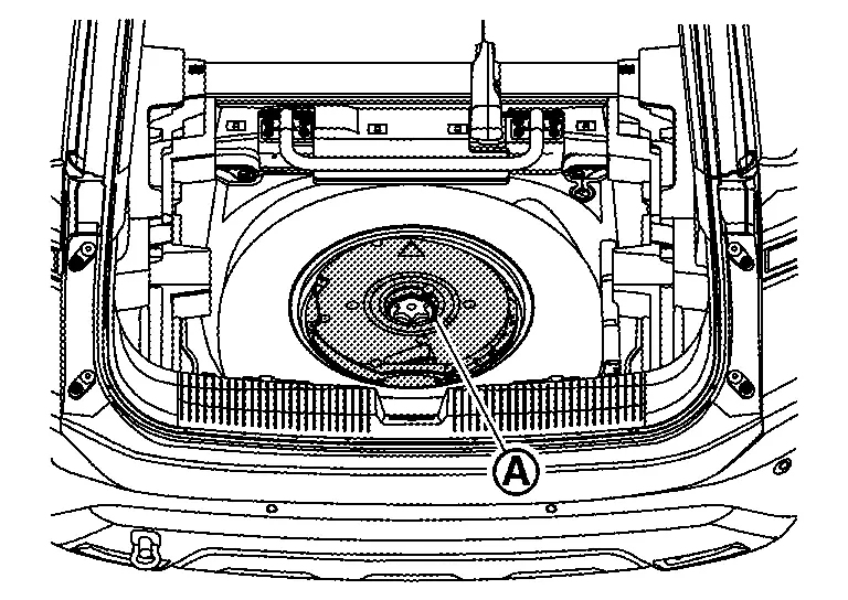
Disconnect the sub woofer connector, and then remove the sub woofer.
INSTALLATION
Installation is in the reverse order of removal.
Front Usb Media Module
Removal and Installation
REMOVAL
Remove the instrument lower panel center. Refer to Removal and Installation.
Release the pawls and remove the front USB media module.
|
: Pawl |
INSTALLATION
Installation is in the reverse order of removal.
Microphone
Removal and Installation
REMOVAL
Remove the map lamp assembly. Refer to Removal and Installation.
Release the microphone pawls, then remove the microphone.
|
:pawl |
INSTALLATION
Installation is in the reverse order of removal.
Active Noise Control Microphone
Front
Removal and Installation
REMOVAL
Remove the headlining assembly. Refer to Removal and Installation.
Disconnect the active noise control microphone harness connector.
Release the pawls, and then remove the active noise control microphone.
Models without Moonroof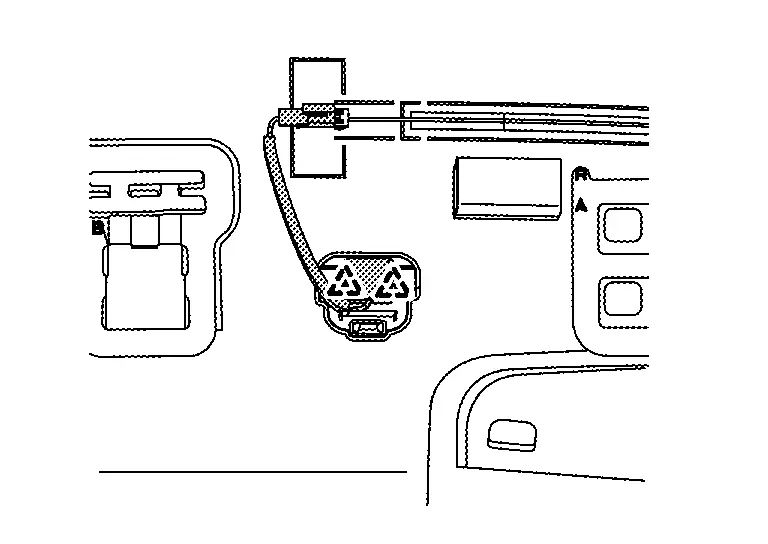
Models with Moonroof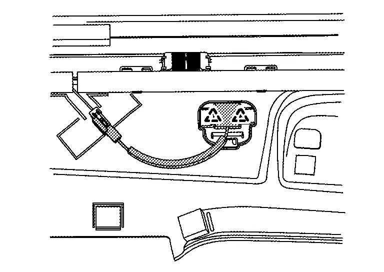
|
: Pawl |
CAUTION:
Carefully handle the pawl fixing the active noise control microphone because the pawl is fragile.
INSTALLATION
Installation is in the reverse order of removal.
NOTE:
Check the active noise control microphone for looseness after the installation.
Rear
Removal and Installation
REMOVAL
Remove the headlining assembly. Refer to Removal and Installation.
Disconnect the active noise control microphone harness connector.
Release the pawls, and then remove the active noise control microphone.
Models without Moonroof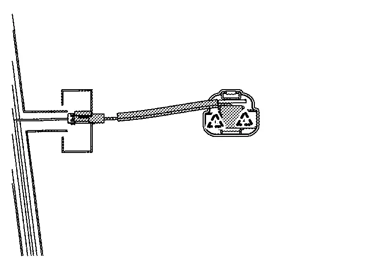
Models with Moonroof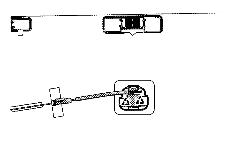
|
: Pawl |
CAUTION:
Carefully handle the pawl fixing the active noise control microphone because the pawl is fragile.
INSTALLATION
Installation is in the reverse order of removal.
NOTE:
Check the active noise control microphone for looseness after the installation.
Steering Switches
Removal and Installation
REMOVAL
For servicing the Japan production steering switches, service the Japan production steering wheel. Refer to Removal and Installation.
NOTE:
The Japan production steering switches are serviced as an assembly with the Japan production ASCD steering switch (if so equipped), the Japan production ProPILOT Assist 1.1 steering switch (if so equipped), the Japan production ProPILOT Assist 2.1 steering switch (if so equipped), the Japan production paddle shifter, and the Japan production steering wheel.
For servicing the USA production steering switches, continue with this procedure.
NOTE:
The USA production steering switches are serviced as a kit with the USA production ASCD steering switch (if so equipped) or the USA production ProPILOT Assist 1.1 steering switch (if so equipped).
Remove the driver air bag module. Refer to Removal and Installation.
Remove the screws from the steering wheel lower finisher.
Using a suitable tool, release the pawls and remove the steering wheel lower finisher.
Using a suitable tool, release the pawls and separate the steering switches from the steering wheel spoke (LH).
Disconnect the harness connector from the steering switches.
Using a suitable tool, release the pawls and separate the ASCD steering switch (if so equipped) or the ProPILOT Assist 1.1 steering switch (if so equipped) from the steering wheel spoke (RH).
Disconnect the harness connector from the ASCD steering switch (if so equipped) or the ProPILOT Assist 1.1 steering switch (if so equipped).
INSTALLATION
Installation is in the reverse order of removal.
CAUTION:
Perform the "ACTION TEST". Refer to Work Procedure (ProPILOT Assist 1.1 and 7 inch Information Display) or to Work Procedure (ProPILOT Assist 1.1 and FULL TFT METER).
Gps Antenna
Removal and Installation
REMOVAL
Remove the instrument panel assembly. Refer to Removal and Installation.
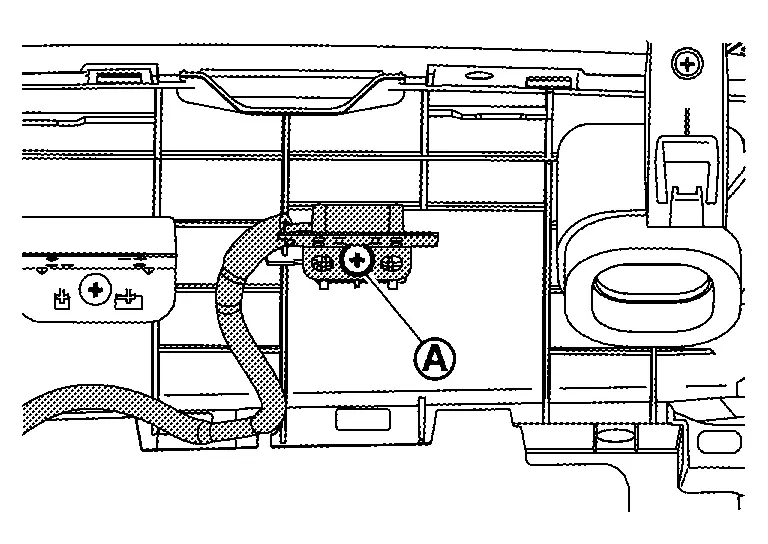
Remove the mounting screw (A) to remove the GPS antenna from the instrument panel.
INSTALLATION
Installation is in the reverse order of removal.
Roof Antenna
With Propilot Assist 2.1
Exploded View
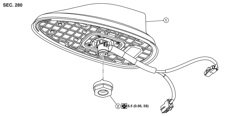
 |
Roof antenna |  |
Nut |
 |
: N·m (kg-m, in-lb) | ||
Removal and Installation
REMOVAL
Remove the headlining assembly. Refer to Removal and Installation.
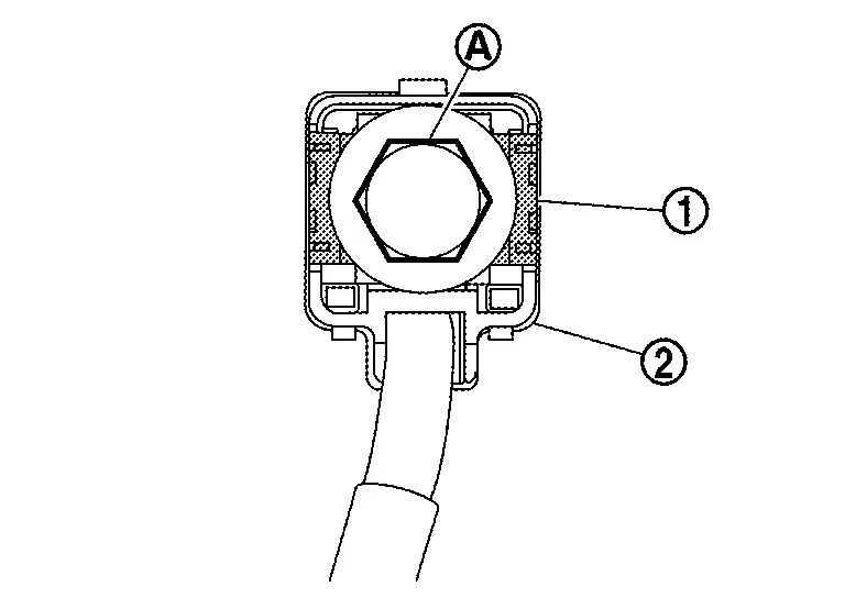
Remove the nut (1).
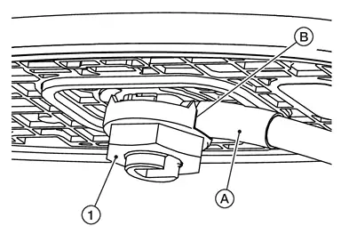
| A. | :Wire harness |
| B. | :Slot in nut |
Disconnect the roof antenna connectors, and then remove the roof antenna.
INSTALLATION
-
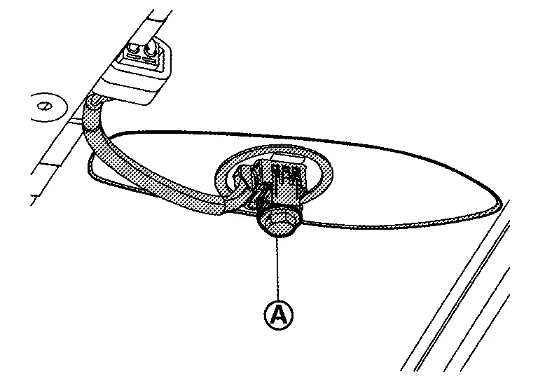
Insert the antenna assembly into the roof.
-
Loosely install the nut (1), making sure the wire harness (A) is in the slot (B) of the nut. Secondly, tighten the nut to specifiation.
CAUTION:
-
Be careful about tightening torque. Antenna sensitivity becomes poor, and when it is excessive, roof panel may be deformed, when roof antenna nut tightening torque is loose.
Without Propilot Assist 2.1
Exploded View
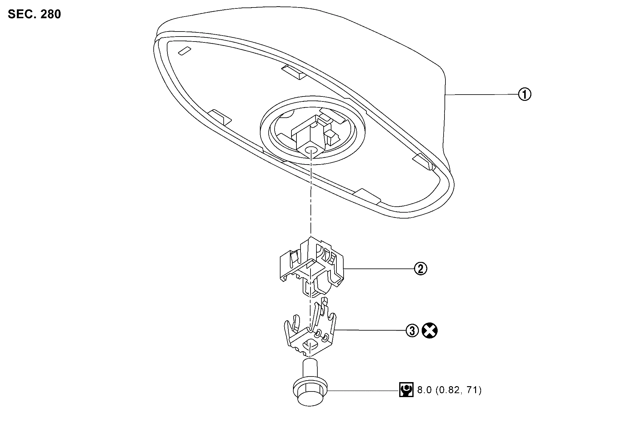
|
Roof antenna | |
Antenna holder |  |
Washer |
|
: N·m (kg-m, in-lb) | ||||
 |
: Always replace after every disassembly. | ||||
Removal and Installation
REMOVAL
Remove the headlining assembly. Refer to Removal and Installation.
Remove the mounting bolt (A), and then remove the washer (1) and antenna holder (2).
Disconnect the roof antenna connector, and then remove the roof antenna.
INSTALLATION
-
Insert the antenna assembly into the roof.
-
Tighten the pre-assembled (bolts, washers, holder) mounting bolts (A).
NOTE:
If only bolt, washer or antenna holder needs to be replaced, it can be ordered separately.
CAUTION:
-
Be careful about tightening torque. Antenna sensitivity becomes poor, and when it is excessive, roof panel may be deformed, when roof antenna mounting bolt tightening torque is loose.
-
Be sure to replace the washer during installation (not reusable).
-
Be sure to replace antenna holder as well, if the antenna holder is cracked or damaged.
Antenna Feeder
Feeder Layout
Models without Moonroof
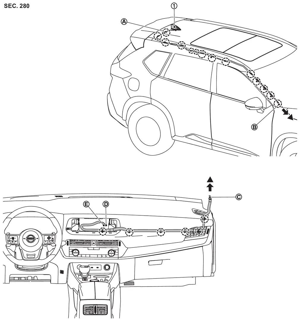
| 1. | Roof antenna | — | — | — | — |
| A | Connector R102 | B | Connector R100 | C | Connector M129 |
| D |
|
E |
|
— | — |
|
: Clip | ||||
 |
: Indicates that the part is connected at points with same symbol in actual Nissan Ariya vehicle. | ||||
Models with Moonroof
| 1. | Roof antenna | — | — | — | — |
| A | Connector R102 | B | Connector R100 | C | Connector M129 |
| D |
|
E |
|
— | — |
|
: Clip | ||||
|
: Indicates that the part is connected at points with same symbol in actual Nissan Ariya vehicle. | ||||
Other materials:
Head restraints/headrests
Basic information
WARNING
Head restraints/headrests work together with other vehicle safety systems to help reduce the risk of injury.
They may provide additional protection in certain rear-end collisions. For maximum effectiveness, adjustable head restraints/headrests must be positioned correctl ...
Symptom Diagnosis. Interior Lighting System Symptoms
Symptom Table
NOTE:
Perform self diagnosis result with CONSULT before the symptom diagnosis. Perform the trouble diagnosis if any DTC is detected.
Symptom Possible cause Inspection item
All the following lamps do not turn ON:
Map lamp assembly
Room lamp
Personal lamp
Lu ...
P0420 Three Way Catalyst Function
DTC Description
The ECM monitors the switching frequency ratio of air fuel ratio (A/F) sensor 1 and heated oxygen sensor 2.A
three way catalyst (manifold) with high oxygen storage capacity will
indicate a low switching frequency of heated oxygen sensor 2. As oxygen
storage capacity decreases, ...