Nissan Rogue (T33) 2021-Present Service Manual: P0420 Three Way Catalyst Function
DTC Description
The ECM monitors the switching frequency ratio of air fuel ratio (A/F) sensor 1 and heated oxygen sensor 2.
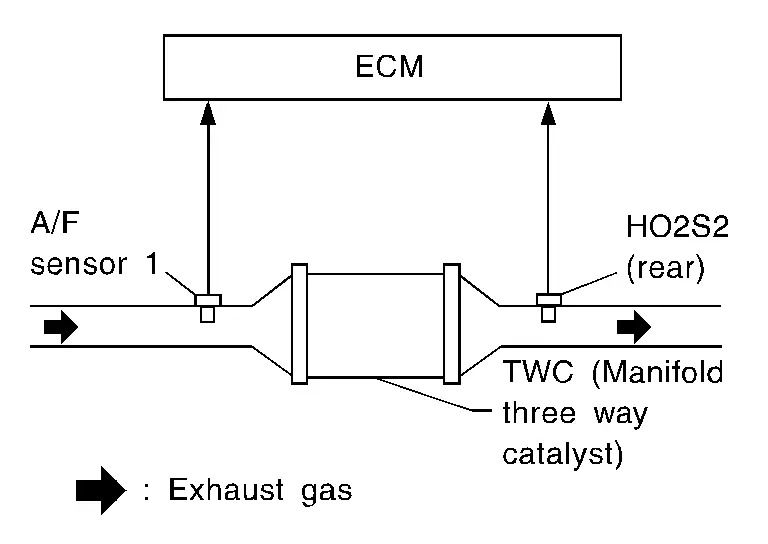
A three way catalyst (manifold) with high oxygen storage capacity will indicate a low switching frequency of heated oxygen sensor 2. As oxygen storage capacity decreases, the heated oxygen sensor 2 switching frequency will increase.
When the frequency ratio of air fuel ratio (A/F) sensor 1 and heated oxygen sensor 2 approaches a specified limit value, the three way catalyst (manifold) malfunction is diagnosed.
DTC DETECTION LOGIC
| DTC |
CONSULT screen terms (Trouble diagnosis content) |
DTC detection condition | ||
| P0420 | 00 |
TW CATALYST SYS-B1 (Catalyst system efficiency below threshold bank 1) |
Diagnosis condition | ŌĆö |
| Signal (terminal) | ŌĆö | |||
| Threshold |
|
|||
| Diagnosis delay time | ŌĆö | |||
POSSIBLE CAUSE
-
Three way catalyst (manifold)
-
Exhaust tube
-
Intake air leaks
-
Exhaust air leaks
-
Fuel injector
-
Fuel injector leaks
-
Spark plug
-
Improper ignition timing
FAIL-SAFE
Not applicable
DTC CONFIRMATION PROCEDURE
PRECONDITIONING
If DTC Confirmation Procedure has been previously conducted, always perform the following procedure before conducting the next test.
TESTING CONDITION:
Do not hold engine speed for more than the specified minutes below.
-
Turn ignition switch OFF and wait at least 10 seconds.
-
Turn ignition switch ON.
-
Turn ignition switch OFF and wait at least 10 seconds.
Will CONSULT be used?
YES>>GO TO 2.
NO>>GO TO 5.
PERFORM DTC CONFIRMATION PROCEDURE-1
 With CONSULT
-
Turn ignition switch ON and select ŌĆ£DATA MONITORŌĆØ mode of ŌĆ£ENGINEŌĆØ using CONSULT.
-
Start engine and warm it up to the normal operating temperature.
-
Turn ignition switch OFF and wait at least 10 seconds.
-
Start engine and keep the engine speed between 3,500 and 4,000 rpm for at least 1 minute under no load.
-
Let engine idle for 1 minute.
-
Check that ŌĆ£COOLANT TEMP/SŌĆØ indicates more than 70┬░C (158┬░F).
If not, warm up engine and go to next step when ŌĆ£COOLANT TEMP/SŌĆØ indication reaches to 70┬░C (158┬░F).
-
Open engine hood.
-
Select ŌĆ£DTC & SRT CONFIRMATIONŌĆØ then ŌĆ£SRT WORK SUPPORTŌĆØ mode of ŌĆ£ENGINEŌĆØ using CONSULT.
-
Rev engine up to 2,000 to 3,000 rpm and hold it for 3 consecutive minutes then release the accelerator pedal completely.
-
Check the indication of ŌĆ£CATALYSTŌĆØ.
Which is displayed on CONSULT screen?
CMPLT>>GO TO 4.
INCMP>>GO TO 3.
PERFORM DTC CONFIRMATION PROCEDURE-2
With CONSULT
-
Wait 5 seconds at idle.
-
Rev engine up to 2,000 to 3,000 rpm and maintain it until ŌĆ£INCMPŌĆØ of ŌĆ£CATALYSTŌĆØ changes to ŌĆ£CMPLTŌĆØ.
 NOTE:
NOTE:
It will take approximately 5 minutes.
If ŌĆ£CMPLTŌĆØ is not displayed after 5 minutes, turn ignition switch OFF and cool down the engine. Retry from step 1 when ŌĆ£COOLANT TEMP/SŌĆØ indication reaches to 70┬░C (158┬░F).
Does the indication change to ŌĆ£CMPLTŌĆØ
YES>>GO TO 4.
NO>>GO TO 2.
PERFORM DTC CONFIRMATION PROCEDURE-3
Check 1st trip DTC.
Is 1st trip DTC detected?
YES>>DTC Diagnosis Procedure
NO-1>>To check malfunction symptom before repair: Refer to Intermittent Incident.
NO-2>>Confirmation after repair: INSPECTION END
PERFORM COMPONENT FUNCTION CHECK
 Without CONSULT
NOTE:
Use component function check to check the overall function of the three way catalyst (manifold). During this check, a 1st trip DTC might not be confirmed.
-
Start engine and warm it up to the normal operating temperature.
-
Turn ignition switch OFF and wait at least 10 seconds.
-
Restart engine and keep the engine speed between 3,500 and 4,000 rpm for at least 1 minute under no load.
-
Let engine idle for 1 minute.
-
Open engine hood.
-
Check the voltage between ECM harness connector terminals as per the following condition.
ECM Condition Voltage (V) Connector + ŌłÆ Terminal F71 92 97 Keeping engine speed at 2500 rpm constant under no load The voltage fluctuation cycle takes more than 5 seconds.
1 cycle: 0.6 - 1.0 ŌåÆ 0 - 0.3 ŌåÆ 0.6 - 1.0
Is the inspection result normal?
YES-1>>To check malfunction symptom before repair: Refer to Intermittent Incident.
YES-2>>Confirmation after repair: INSPECTION END
NO>>DTC Diagnosis Procedure
DTC Diagnosis Procedure
CHECK EXHAUST SYSTEM
Visually check exhaust tubes, three way catalyst and muffler for dent.
Is the inspection result normal?
YES>>GO TO 2.
NO>>Repair or replace error-detected parts. Refer to Exploded View.
CHECK EXHAUST GAS LEAK
-
Start engine and run it at idle.
-
Listen for an exhaust gas leak before the three way catalyst (manifold).
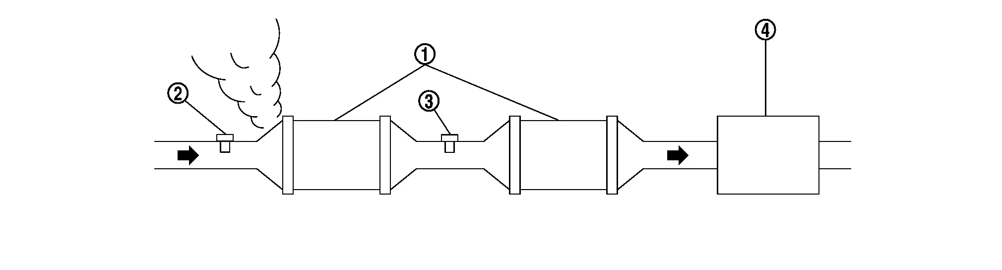

Three way catalyst 
A/F sensor 1 
HO2S2 
Muffler
Is the inspection result normal?
YES>>GO TO 3.
NO>>Repair or replace error-detected parts. Refer to Exploded View.
CHECK INTAKE AIR LEAK AND PCV HOSE
-
Start engine and let it idle.
-
Listen for an intake air leak after the mass air flow sensor.
Is the inspection result normal?
YES>>GO TO 4.
NO>>Repair or replace error-detected parts. Refer to Exploded View.
CHECK IGNITION TIMING AND IDLE SPEED
Check the following items:
For specification, Refer to IGNITION TIMING : Service Data.
For specification, Refer to IDLE SPEED : Service Data.
Is the inspection result normal?
YES>>GO TO 5.
NO>>Refer to Exploded View.
CHECK FUEL INJECTOR
Check the fuel injector. Refer to Diagnosis Procedure.
Is the inspection result normal?
YES>>GO TO 6.
NO>>Refer to Diagnosis Procedure.
CHECK FUNCTION OF IGNITION COIL-1
CAUTION:
Do the following procedure in the place where ventilation is good without the combustible.
-
Turn ignition switch OFF.
-
Remove fuel pump fuse in IPDM E/R to release fuel pressure.
NOTE:
Do not use CONSULT to release fuel pressure, or fuel pressure applies again during the following procedure.
-
Start engine.
-
After engine stalls, crank it two or three times to release all fuel pressure
-
Turn ignition switch OFF.
-
Remove all ignition coil harness connectors to avoid the electrical discharge from the ignition coils.
-
Remove ignition coil and spark plug of the cylinder to be checked. Refer to Removal and Installation.
-
Crank engine for 5 seconds or more to remove combustion gas in the cylinder.
-
Connect spark plug and harness connector to ignition coil.
-
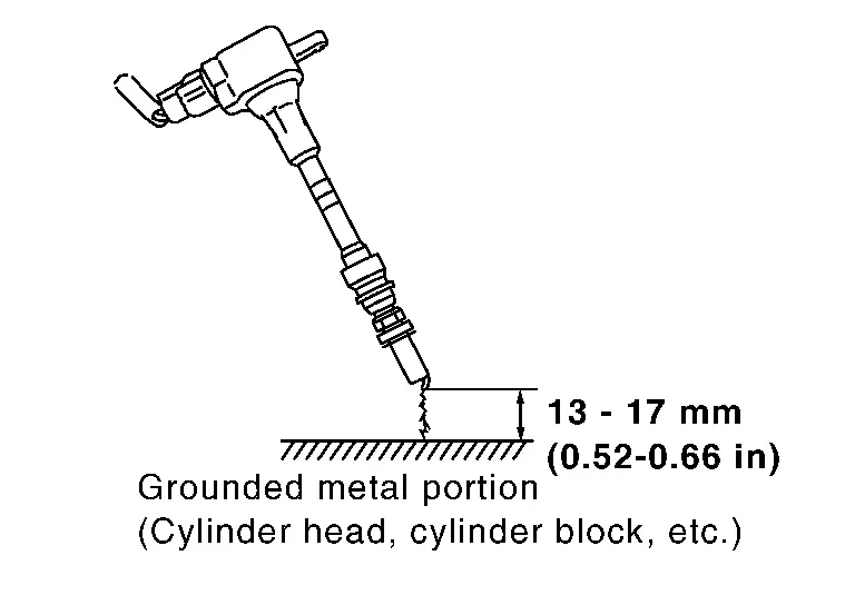
Fix ignition coil using a rope etc. with gap of 13 - 17 mm (0.52 - 0.66 in) between the edge of the spark plug and grounded metal portion as shown in the figure.
-
Crank engine for about 3 seconds, and check whether spark is generated between the spark plug and the grounded metal portion.
CAUTION:
-
Do not approach to the spark plug and the ignition coil within 50 cm (19.7 in). Be careful not to get an electrical shock while checking, because the electrical discharge voltage becomes 20 kV or more.
-
It might cause to damage the ignition coil if the gap of more than 17 mm (0.66 in) is taken.
NOTE:
When the gap is less than 13 mm (0.52 in), the spark might be generated even if the coil is malfunctioning.
-
Is the inspection result normal?
YES>>GO TO 11.
NO>>GO TO 7.
CHECK FUNCTION OF IGNITION COIL-2
-
Turn ignition switch OFF.
-
Disconnect spark plug and connect a known-good spark plug.
-
Crank engine for about 3 seconds, and recheck whether spark is generated between the spark plug and the grounded metal portion.
Spark should be generated.
Is the inspection result normal?
YES>>GO TO 8.
NO>>Check ignition coil, power transistor and their circuits. Refer to Diagnosis Procedure.
CHECK SPARK PLUG-1
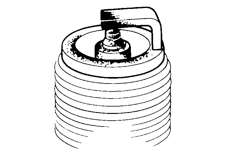
Check the initial spark plug for fouling, etc.
Is the inspection result normal?
YES>>Replace spark plug(s) with standard type one(s). For spark plug type, Refer to Spark Plug.
NO>>Repair or clean spark plug.Refer to Removal and Installation. Then GO TO 9.
CHECK SPARK PLUG-2
Check spark plug. Refer to Component Inspection.
Is the inspection result normal?
YES>>GO TO 10.
NO>>Repair or replace error-detected parts.
CHECK FUNCTION OF IGNITION COIL-3
-
Reconnect the initial spark plugs.
-
Crank engine for about 3 seconds, and recheck whether spark is generated between the spark plug and the grounded portion.
Spark should be generated.
Is the inspection result normal?
YES>>INSPECTION END
NO>>Replace spark plug(s) with standard type one(s). For spark plug type, Refer to Spark Plug.
PERFORM DTC CONFIRMATION PROCEDURE
-
Replace three way catalyst (manifold). Refer to Removal and Installation.
-
Perform DTC confirmation procedure. DTC Description
Is DTC P0420 detected again?
YES>>Replace all fuel injector. Removal and Installation and Removal and Installation.
NO>>INSPECTION END
Other materials:
Automatic Brake Hold. Removal and Installation
Chassis Control Module
Removal and Installation
Removal and installation procedure of chassis control module. Refer to Removal and Installation.
Automatic Brake Hold Switch
Removal and Installation
Removal and installation procedure of parking brake switch. Refer to Removal and Installation.NOTE: ...
Additional Service When Replacing Around View Monitor Control Unit
Description
CAUTION:
When replacing the around view monitor control unit, always replace
it with a new one. Intelligent around view monitor system does not
operate properly in case of reuse of the around view monitor control
unit from another Nissan Ariya vehicle.
When before writin ...
Three Way Catalyst
Exploded View
Air fuel ratio (A/F) sensor 1
Manifold washer
Stud bolt
Catalyst support bracket
Three way catalyst
Heated oxygen sensor 2
Turbo gasket (OUT)
V-band clamp
Comply with the assembly procedure when tightening. Refer to Remo ...