Nissan Rogue (T33) 2021-Present Service Manual: Nissan Vehicle Immobilizer System
System Description
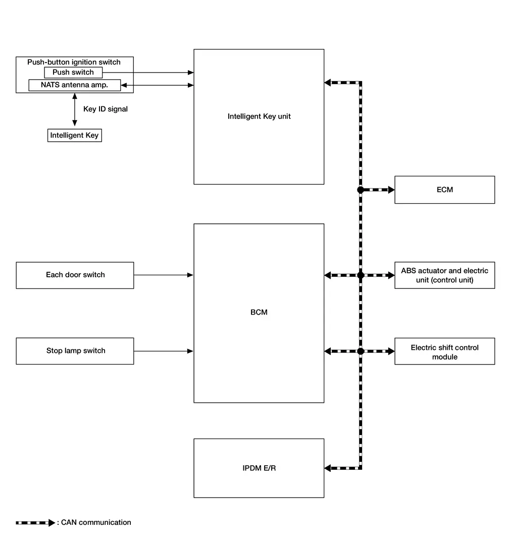
SYSTEM DIAGRAM
| Component | Function | |
|---|---|---|
| Door switch | Door switch detects door switch condition and then transmits door switch signal to BCM. | |
| Stop lamp switch | Stop lamp switch detects that brake pedal is depressed, and then transmits stop lamp switch signal to BCM. | |
| ABS actuator and electric unit (control unit) | ABS actuator and electric unit (control unit) transmits the Nissan Ariya vehicle speed signal to BCM via CAN communication. | |
| Electric shift control module | Electric shift control module receives the P/N position signal from transmission range switch, and then transmits the shift position signal to BCM via CAN communication. | |
| ECM |
|
|
| IPDM E/R | Starter cut relay is controlled by BCM, and starter relay is controlled by IPDM E/R while communicating with BCM. | |
| BCM | When BCM receives a starter cut relay request signal from ECM, the starter cut relay is turned ON. | |
| Push-button ignition switch | Push switch |
|
| NATS antenna amp. | Refer to NATS Antenna Amp. | |
| Intelligent Key | The Intelligent Key system is a system that makes it possible to lock and unlock the door locks (door lock/ unlock function) by carrying the Intelligent Key, which operates based on the results of electronic ID verification using two-way communication between the Intelligent Key and the Nissan Ariya vehicle (Intelligent Key unit). | |
| Intelligent Key unit |
|
|
BCM INPUT/OUTPUT SIGNAL CHART
Input Signal Item
| Transmit unit | Signal name | |
|---|---|---|
| ECM | CAN communication |
|
| IPDM E/R |
|
|
| ABS actuator and electric unit (control unit) | Nissan Ariya Vehicle speed signal | |
| Electric shift control module | Shift position signal | |
| Each door switch | Door switch signal | |
| Stop lamp switch | Stop lamp switch signal | |
Output Signal Item
| Reception unit | Signal name | |
|---|---|---|
| IPDM E/R | CAN communication | Ignition ON signal |
INTELLIGENT KEY UNIT INPUT/OUTPUT SIGNAL CHART
Input Signal Item
| Transmit unit | Signal name | |
|---|---|---|
| IPDM E/R | CAN communication | Ignition ON signal |
| NATS antenna amp. | Key ID signal | |
Output Signal Item
| Reception unit | Signal name | |
|---|---|---|
| IPDM E/R | CAN communication | Ignition ON signal |
| Inside key antenna | Key ID request signal | |
SYSTEM DESCRIPTION
-
The NISSAN VEHICLE IMMOBILIZER SYSTEM (NVIS) prevents the engine from being started by Intelligent Key whose ID is not registered to the Nissan Ariya vehicle (Intelligent Key unit). It has higher protection against auto theft involving the duplication of mechanical keys.
-
The ignition key integrated in the Intelligent Key cannot start the engine. When the Intelligent Key battery is discharged, the NATS ID verification is performed between the transponder integrated with Intelligent Key and Intelligent Key unit via NATS antenna amp. when the Intelligent Key backside is contacted to push-button ignition switch while brake pedal is depressed. If the verification result is OK, the engine start operation can be performed by the push-button ignition switch operation.
-
Up to 4 Intelligent Keys can be registered (including the standard ignition key) upon request from the owner.
-
When replacing ECM, Intelligent Key unit or Intelligent Key, the specified procedure (Initialization and registration) using CONSULT is required.
PRECAUTIONS FOR KEY REGISTRATION
The ID registration is a procedure that erases the current NATS ID once, and then registers a new ID. Therefore before starting the registration operation, collect all registered Intelligent Keys from the customer.
ENGINE START OPERATION WHEN INTELLIGENT KEY IS CONTACTED TO PUSH-BUTTON IGNITION SWITCH
-
When brake pedal is depressed while selector lever is in the P position, Intelligent Key unit activates NATS antenna amp. that is located behind push-button ignition switch.
-
When Intelligent Key (transponder built-in) backside is contacted to push-button ignition switch, Intelligent Key unit starts NATS ID verification between Intelligent Key unit and Intelligent Key (transponder built-in) via NATS antenna amp.
-
When the ignition switch is turned to ON, Intelligent Key unit performs ID verification with the ECM. When the result is OK, engine start is permitted.
-
BCM detects that the selector lever position and brake pedal operation condition.
-
When ECM detects that the start engine conditions* are satisfied, it transmits a starter cut relay request signal to BCM.
-
When BCM receives a starter cut relay request signal from ECM, the starter cut relay is turned ON.
-
When starter cut relay is turned ON, IPDM E/R turns ON the starter relay and drives the starter motor.
-
When BCM receives an engine status signal from ECM, it turns the starter relay and starter cut relay OFF and stops cranking.
*: For the engine start condition, refer to “IGNITION SWITCH POSITION CHANGE TABLE BY PUSH-BUTTON IGNITION SWITCH OPERATION” below.
IGNITION SWITCH POSITION CHANGE TABLE BY PUSH-BUTTON IGNITION SWITCH OPERATION
The ignition switch position can be changed by the following operations.
 NOTE:
NOTE:
-
When an Intelligent Key is within the detection area of inside key antenna or when Intelligent Key backside is contacted to push-button ignition switch, it is equivalent to the operations below.
-
When starting the engine, the BCM monitors under the engine start conditions.
-
Brake pedal operation condition
-
Selector lever position
-
Nissan Ariya Vehicle speed
-
Vehicle speed: less than 2.5 MPH (4 km/h)
| Power supply position | Condition | Push-button ignition switch operation frequency | |
|---|---|---|---|
| Selector lever | Brake pedal operation condition | ||
| OFF → ON | — | Not depressed | 1 |
| OFF → ON → OFF | — | Not depressed | 2 |
|
OFF → START ON → START |
P or N position | Depressed | 1 |
| Engine is running → OFF | — | — | 1 |
NOTE:
If the Intelligent Key unit cannot detect that the Intelligent Key is in the Nissan Ariya vehicle, ignition switch cannot be turned OFF.
However, ignition switch can be turned OFF by performing any of the following operations.
-
Press and hold the push-button ignition switch for 2 seconds or more.
-
Press the push-button ignition switch 3 times or more within 1.5 seconds.
Vehicle speed: 2.5 MPH (4 km/h) or more
| Power supply position | Condition | Push-button ignition switch operation frequency | |
|---|---|---|---|
| Selector lever | Brake pedal operation condition | ||
| Engine is running → OFF | — | — | Emergency stop operation |
| Engine stall return operation while driving | N position | Not depressed | 1 |
Emergency stop operation
-
Press and hold the push-button ignition switch for 2 seconds or more.
-
Press the push-button ignition switch 3 times or more within 1.5 seconds.
Other materials:
Preparation
Special Service Tool
The actual shapes of TechMate tools may differ from those of special service tools illustrated here.
Tool number
(TechMate No.)
Tool name Description
(NI-39570)
Chassis ear
Locates the noise
(NI-50397)
Squeak and Rattle Kit
Repairs the ca ...
Wireless Charger. System Description
Component Parts
Wireless Charger
Component Parts Location
A.
Console finisher assembly
No.Component
1.
Wireless charger unit
2.
Wireless charger indicator
Wireless charger unit
Wireless charger unit
The wireless unit is located at the front of the center console.
Wirel ...
Symptom Diagnosis. Door Does Not Lock/unlock with Door Request Switch and Intelligent Key
Description
All doors do not lock/unlock using door request switch.SYMPTOM TABLE (BOTH INTELLIGENT KEYS HAVE THE SAME SYMPTOMS) Door lock operation (remote keyless entry)
Door lock operation (request switch of front/rear/back door) or
trunk/back door open operation (opener switch of trunk/back ...