Nissan Rogue (T33) 2021-Present Service Manual: Manual Air Conditioning :: Ecu Diagnosis Information
A/c Amp.
Values on the Diagnosis Tool
 NOTE:
NOTE:
The following table includes information (items) inapplicable to this Nissan Ariya vehicle. For information (items) applicable to this vehicle, refer to CONSULT display items.
| Monitor item | Condition | Value/Status | |
|---|---|---|---|
| FAN REQ SIG | Engine: Run at idle after warming up | Front blower motor: ON | On |
| Front blower motor: OFF | Off | ||
| A/C compressor clutch status | Engine: Run at idle after warming up | A/C switch: ON | On |
| A/C switch: OFF | Off | ||
| Compressor request signal | Engine: Run at idle after warming up | A/C switch: ON | On |
| A/C switch: OFF | Off | ||
| ODO/TRIP METER | Ignition switch ON | Equivalent to odometer reading | |
| Rear XM |
This item is displayed, but cannot be monitored. |
||
| XM |
This item is displayed, but cannot be monitored. |
||
| PASS IN CAL |
This item is displayed, but cannot be monitored. |
||
| Nissan Ariya Vehicle speed | When driving the vehicle | Equivalent to speedometer reading | |
| AMB TEMP SEN | Ignition switch ON |
Equivalent to ambient temperature [Display range: -50 - 70┬░C (-58 - 158┬░F)] |
|
| Intake temperature sensor value | Ignition switch ON |
Equivalent to evaporator fin temperature [Display range: -40 - 100┬░C (-40 - 212┬░F)] |
|
| In-Nissan Ariya vehicle temperature sensor |
This item is displayed, but cannot be monitored. |
||
| Blower fan duty | Engine: Run at idle after warming up | Front blower motor: ON |
|
| Front blower motor: OFF | 0 | ||
| Assist seat target air temperature |
This item is displayed, but cannot be monitored. |
||
| Engine RPM | Engine: Running | Equivalent to tachometer reading | |
| Engine coolant temperature | Ignition switch ON | Equivalent to engine coolant temperature | |
| Sunload sensor calculation value |
This item is displayed, but cannot be monitored. |
||
| Intake temperature sensor calculation value | Ignition switch ON |
Equivalent to evaporator fin temperature [Display range: -40 - 100┬░C (-40 - 212┬░F)] |
|
| In-Nissan Ariya vehicle temperature sensor value |
This item is displayed, but cannot be monitored. |
||
| Ambient temperature sensor calculation value | Ignition switch ON |
Equivalent to ambient temperature [Display range: -40 - 100┬░C (-40 - 212┬░F)] |
|
| Sun load sensor value |
This item is displayed, but cannot be monitored. |
||
Reference Value
TERMINAL LAYOUT
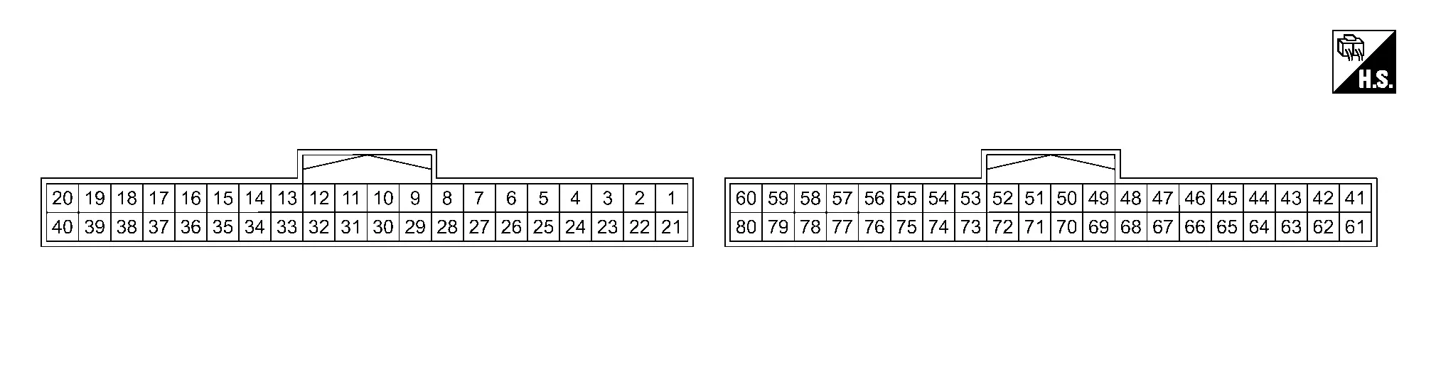
PHYSICAL VALUES
|
Terminal No. (Wire color) | Description | Condition |
Value (Approx.) | ||||
|---|---|---|---|---|---|---|---|
| (+) | (ŌłÆ) | Signal name | Input/Output | ||||
|
1 (LA/LG) |
58 (B) |
Door motor power supply | Output | Ignition switch ON | Battery voltage | ||
|
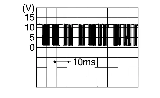
2 (LA/G) |
58 (B) |
LIN communication (door motor) | Input/Output | Ignition switch ON |
|
||
|
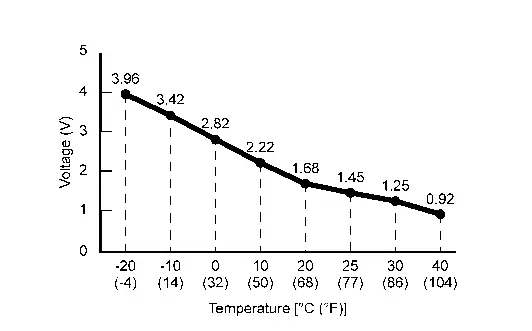
23 (LA/SB) |
26 (BR) |
Intake sensor signal | Input | Ignition switch ON |
|
||
|
26 (BR) |
Ground | Sensor ground (intake) | ŌĆö | Ignition switch ON | 0 V | ||
|
27 (LA/B) |
Ground | Door motor ground | ŌĆö | Ignition switch ON | 0 V | ||
|
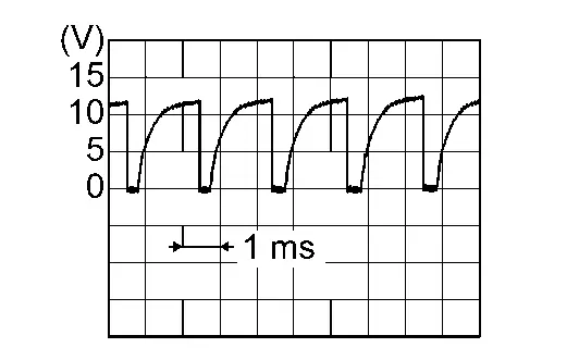
34 (G) |
58 (B) |
Blower motor control | Output | Ignition switch ON | Front blower motor: OFF | Battery voltage | |
| Front blower motor: 1st speed (manual) |
|
||||||
| Front blower motor: 11th speed (manual) |
|
||||||
|
50 (LA/L) |
ŌĆö | CAN-High | Input/Output | ŌĆö | ŌĆö | ||
|
58 (B) |
Ground | Ground | ŌĆö | Ignition switch ON | 0 V | ||
|
60 (LA/R) |
58 (B) |
Accessory power supply | Input | Ignition switch OFF (auto ACC status) or ON | Battery voltage | ||
| Ignition switch OFF (not auto ACC status) | 0 V | ||||||
|
68 (LA/P)1 (LA/Y)2 |
58 (B) |
LIN communication (A/C control) | Input/Output | Ignition switch ON |
|
||
|
70 (LA/P) |
ŌĆö | CAN-Low | Input/Output | ŌĆö | ŌĆö | ||
1: Japan production
2: USA production
Fail-safe
FAIL-SAFE FUNCTION
-
If a CAN communication error exists between the A/C amp., ECM, IPDM E/R, BCM and combination meter for 2 seconds or longer, air conditioning is controlled under the following conditions:
A/C compressor : OFF -
If a LIN communication error exists between the A/C amp. and A/C switch assembly for 30 seconds or longer, air conditioning is controlled under the following conditions:
A/C compressor : Setting before communication error occurs Air outlet : Setting before communication error occurs Air inlet : Setting before communication error occurs Front blower fan speed : Setting before communication error occurs
DTC Index
├Ś: Applicable
| DTC |
Items (CONSULT screen terms) | Fail-safe | Reference |
|---|---|---|---|
| B24A0-49 | A/C AUTO AMP. | ŌĆö | DTC Description |
| B24A1-16 | A/C AUTO AMP. POWER SUPPLY | ŌĆö | DTC Description |
| B24A1-17 | A/C auto AMP. | ŌĆö | DTC Description |
| B24A2-55 | Configuration not implement | ŌĆö | DTC Description |
| B24A4-11 | INTAKE SENSOR | ŌĆö | DTC Description |
| B24A4-15 | INTAKE SENSOR | ŌĆö | DTC Description |
| B24B4-02 | A/C CONTROL COMM | ŌĆö | DTC Description |
| B24C6-12 | BLOWER MOTOR CONTROL | ŌĆö | DTC Description |
| B24C6-14 | BLOWER MOTOR CONTROL | ŌĆö | DTC Description |
| B24F5-93 | Mode door motor | ŌĆö | DTC Description |
| B24F6-93 | Intake door motor | ŌĆö | DTC Description |
| B24F8-93 | Air mix door motor 2 | ŌĆö | DTC Description |
| U1CA1-08 | LIN communication 2 | ŌĆö | DTC Description |
| U1CA2-08 | LIN communication 3 | ŌĆö | DTC Description |
| U1CAA-02 | Mode door motor | ŌĆö | DTC Description |
| U1CAB-02 | Intake door motor | ŌĆö | DTC Description |
| U1CAD-02 | Air mix door motor 2 | ŌĆö | DTC Description |
├Ś: Applicable
| DTC |
Items (CONSULT screen terms) | Fail-safe | Reference |
|---|---|---|---|
| U2140-87 | CAN comm err (ECM) | ŌĆö | DTC Description |
| U2148-87 | CAN comm err (brake control unit) | ŌĆö | DTC Description |
| U214E-87 | CAN comm err (combination meter) | ŌĆö | DTC Description |
| U214F-87 | CAN comm err (BCM) | ŌĆö | DTC Description |
| U2154-87 | CAN comm err (MIU) | ŌĆö | DTC Description |
| U215B-87 | CAN comm err (IPDM E/R) | ŌĆö | DTC Description |
Bcm, Ecm, Ipdm E/r
List of ECU Reference
| ECU | Reference | |
|---|---|---|
| BCM | Values on the Diagnosis Tool | |
| Reference Value (With Type A Meter) | ||
| Reference Value (With Type B Meter) | ||
| Fail-safe | ||
| DTC Inspection Priority Chart | ||
| DTC Index | ||
| ECM | Values On The Diagnosis Tool | |
| Physical Values | ||
| Fail-safe | ||
| DTC Inspection Priority Chart | ||
| DTC Index | ||
| Test Value and Test Limit | ||
| IPDM E/R | Values on the Diagnosis Tool | |
| Reference Value | ||
| Fail-safe | ||
| DTC Inspection Priority Chart | ||
| DTC Index | ||
Other materials:
Input Speed Sensor
Exploded View
1.
O-ring
2.
Input speed sensor
3.
Transaxle assembly
: N┬Ęm (kg-m, in-lb) : Always replace after every disassembly. : Apply petroleum jelly.
Removal and Installation
REMOVAL Never Reuse These Parts Part Code For additional information:
Seal-O-ring
31051 ...
P062d Fuel Injector Driver Bank 1
DTC Description
DTC DETECTION LOGIC DTC
CONSULT screen terms
(Trouble diagnosis content)
DTC detection condition
P062D
00
Fuel injector driver bank 1
(Fuel Injector Driver Circuit Performance Bank 1)
Diagnosis condition
Battery voltage: 10 V or more
Signal (terminal) ...
Steering Switch Signal a Circuit
Component Function Check
CHECK COMBINATION METER INPUT SIGNAL
CONSULT
Ignition switch ON.
Select ŌĆ£Steering switch inputŌĆØ in ŌĆ£Data monitorŌĆØ mode of ŌĆ£M&AŌĆØ.
Check that the function operates normally according to the following conditions:
Condition Value
CONTRO ...