Nissan Rogue (T33) 2021-Present Service Manual: Kr15ddt :: Removal and Installation
Fuel Level Sensor Unit, Fuel Filter and Fuel Pump Assembly
Exploded View
REMOVAL
2WD
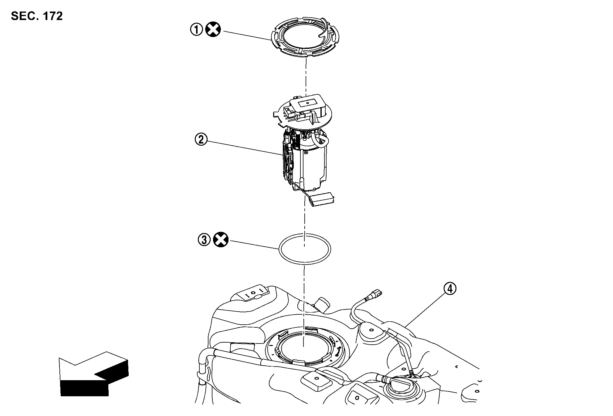
 |
Lock ring |  |
Fuel level sensor unit, fuel filter and fuel pump assembly |  |
O-ring |
 |
Fuel tank | ||||
| : Nissan Ariya Vehicle front | |||||
 |
: Always replace after every disassembly. | ||||
CAUTION:
Never remove or disassemble parts unless instructed as shown in the figure.
AWD
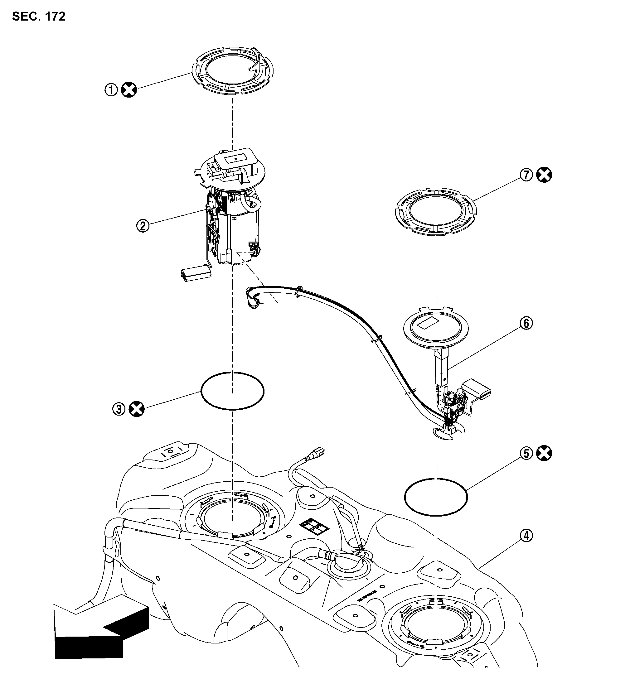
|
Lock ring | |
Fuel level sensor unit, fuel filter and fuel pump assembly | |
O-ring |
|
Fuel tank |  |
O-ring |  |
Sub fuel level sensor assembly |
 |
Lock ring | ||||
| : Nissan Ariya Vehicle front | |||||
|
: Always replace after every disassembly. | ||||
CAUTION:
Never remove or disassemble parts unless instructed as shown in the figure.
DISASSEMBLY
2WD
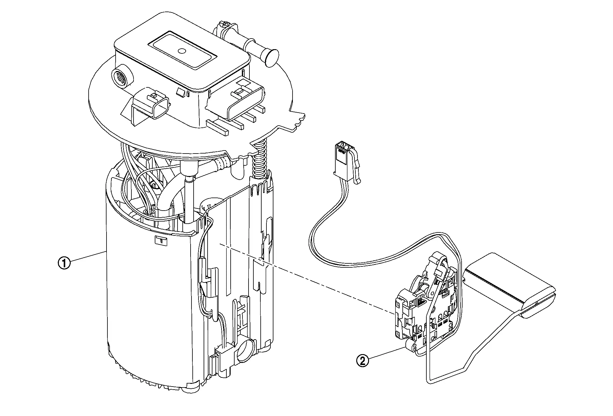
|
Fuel filter and fuel pump assembly | |
Fuel level sensor unit |
AWD
 NOTE:
NOTE:
Fuel level sensor unit cannot be disassembly from fuel level sensor unit, fuel filter and fuel pump assembly.
Removal and Installation
WARNING:
Read ÔÇťGeneral PrecautionsÔÇŁ when working on the fuel system. Refer to General Precautions.
REMOVAL
2WD
CAUTION:
Perform the operation with vehicle on level ground.
Release fuel pressure. Refer to Work Procedure.
Open fuel filler lid.
Insert a general purpose pipe with the dimensions shown in fuel filler cap less unit and release the pressure inside the fuel tank.
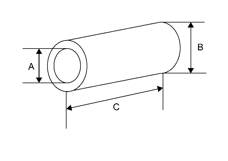
| A | : Over 16 mm (0.63 in) |
| B | : 21.0 mm (0.83 in) |
| C | : 150 mm (5.91 in) |
NOTE:
Insert and hold 80 mm (3.15 in) from the end of the general purpose pipe into the fuel filler port.
Check fuel level on a level ground. If the fuel level is 7/8 of the fuel tank (full or nearly full), draw appropriate amount of fuel from the fuel tank.
| Guideline | : Draw approximately 15 liters (4 US gal, 3-1/4 Imp gal) from a full-tank condition. |
In the event of malfunction in fuel pump, insert a hose measuring 16 mm (0.63 in) in diameter into the filler opening to draw approximately 15 liters (4 US gal, 3-1/4 Imp gal) fuel.
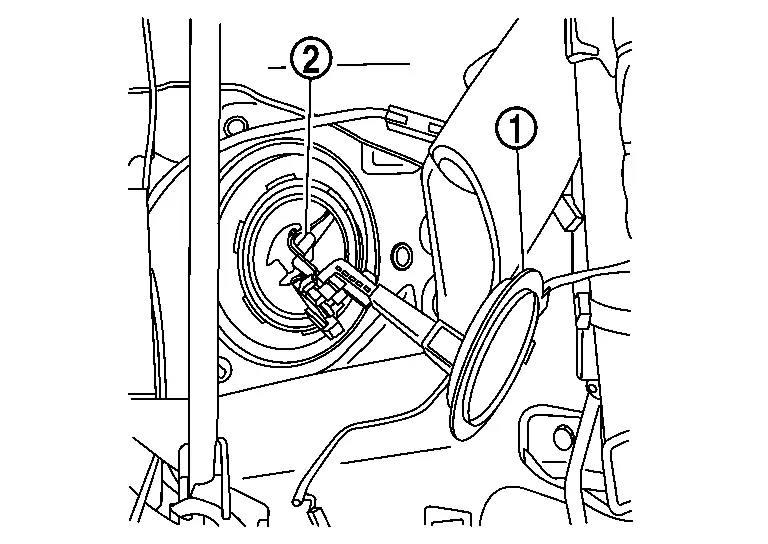
Remove rear seat cushion. Refer to Removal and Installation.
Remove inspection hole cover.
-
Using a screwdriver, remove it by turning clips clockwise by 90 degrees.
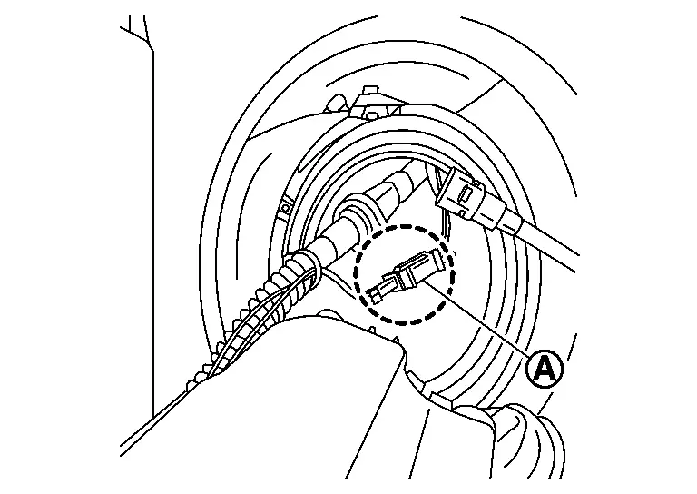
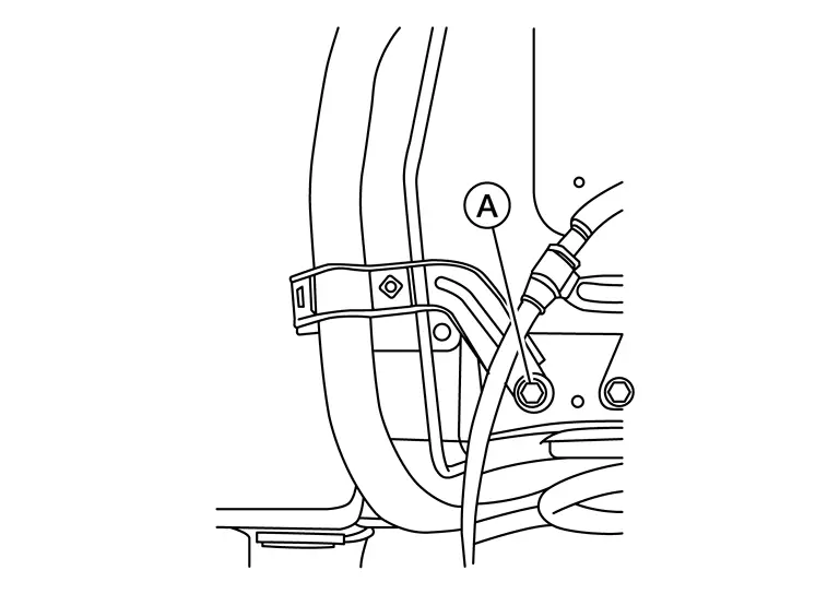
Disconnect harness connectors (2) and (3) and quick connector (5).
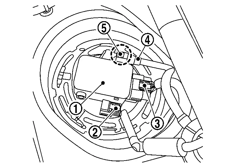
| 1. | : Fuel level sensor unit, fuel filter and fuel pump assembly |
| 4. | : Fuel feed tube |
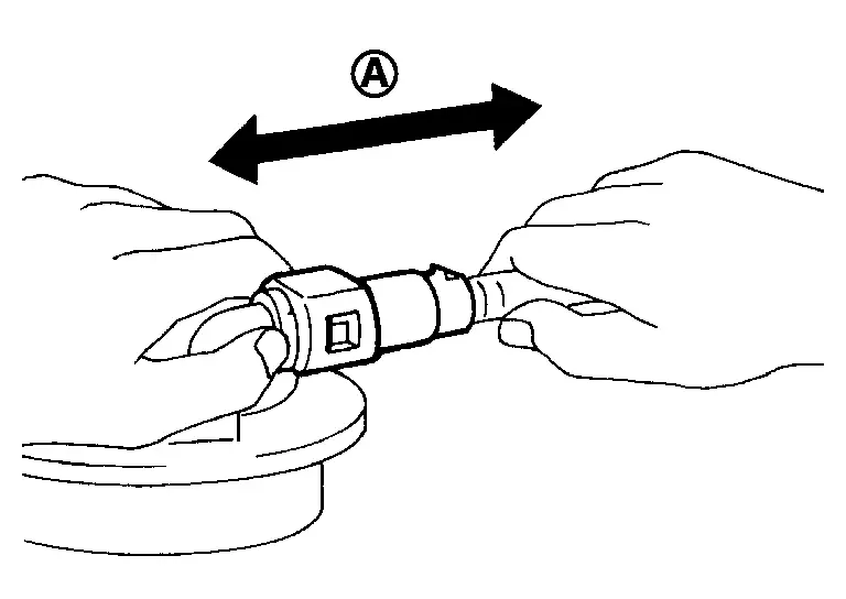
Disconnect quick connector as follows:
-
Hold the sides of connector, push in tabs (B) and pull out fuel feed tube.
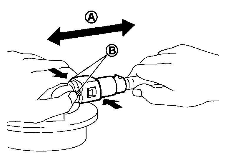
A. : Pull -
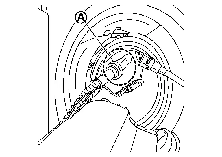
If quick connector sticks to tube of fuel level sensor unit, fuel filter and fuel pump assembly, push and pull quick connector several times until they start to move. Then disconnect them by pulling.
CAUTION:
-
Quick connector (1) can be disconnected when the tabs (F) are completely depressed. Never twist it more than necessary.
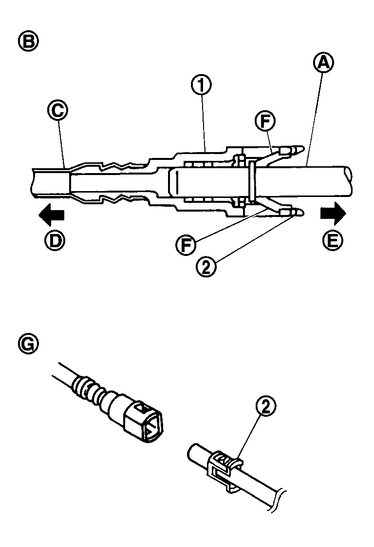
B. : Connection (cross-section) D. : To under floor fuel line E. : To fuel tank G. : Disconnection -
Never use any tools to disconnected quick connector.
-
Keep resin tube (C) away from heat. Be especially careful when welding near the resin tube.
-
Prevent acid liquid such as battery electrolyte, etc. from getting on resin tube.
-
Never bend or twist resin tube during installation and disconnection.
-
Never remove the remaining retainer (2) on hard tube (or the equivalent) (A) except when resin tube or retainer is replaced.
-
When resin tube or hard tube (or the equivalent) is replaced, also replace retainer with new one.
-
To keep the connecting portion clean and to avoid damage and foreign materials, cover them completely with plastic bags (A) or something similar.
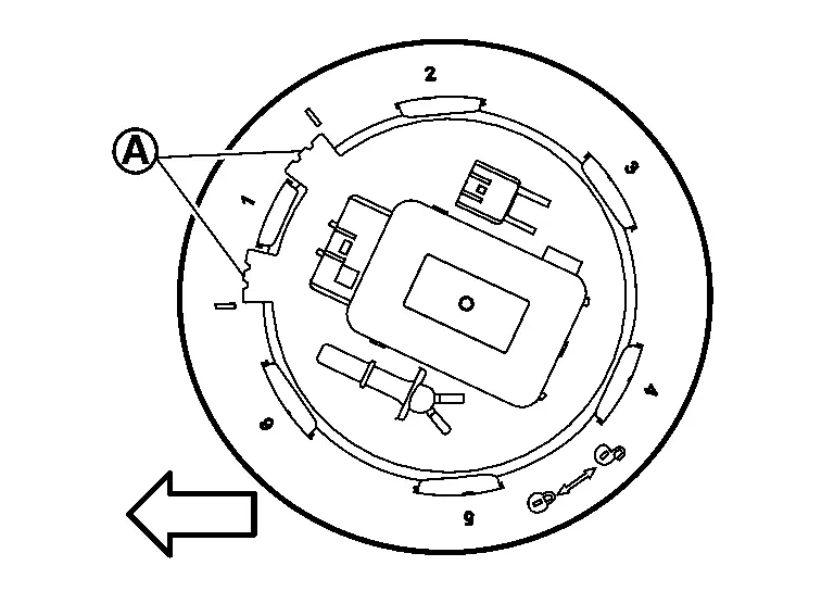
Remove lock ring from fuel level sensor, fuel filter, and fuel pump assembly using Tool (A).
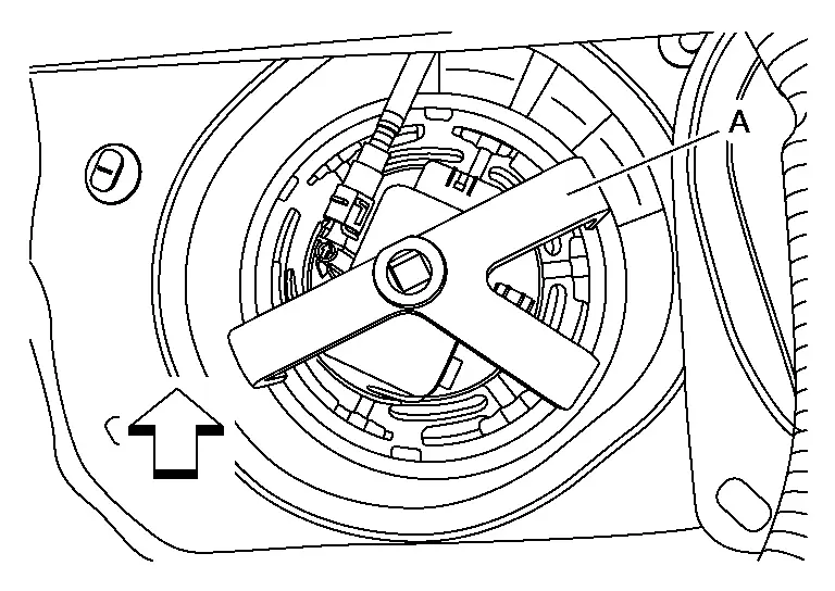
| Tool number (A) |
: (NI-45747) (shown) : KV101207S0 |
 |
: Front |
Remove fuel level sensor unit, fuel filter and fuel pump assembly.
AWD
CAUTION:
Perform the operation with vehicle on level ground.
Release fuel pressure. Refer to Work Procedure.
Open fuel filler lid.
Insert a general purpose pipe with the dimensions shown in fuel filler cap less unit and release the pressure inside the fuel tank.
| A. | : Over 16 mm (0.63 in) |
| B. | : 21.0 mm (0.83 in) |
| C. | : 150 mm (5.91 in) |
NOTE:
Insert and hold 80 mm (3.15 in) from the end of the general purpose pipe into the fuel filler port.
Check fuel level on a level ground. If the fuel level is 7/8 of the fuel tank (full or nearly full), draw appropriate amount of fuel from the fuel tank.
| Guideline | : Draw approximately 15 liters (4 US gal, 3-1/4 Imp gal) from a full-tank condition. |
In the event of malfunction in fuel pump, insert a hose measuring 16 mm (0.63 in) in diameter into the filler opening to draw approximately 15 liters (4 US gal, 3-1/4 Imp gal) fuel.
Remove rear seat cushion. Refer to Removal and Installation.
Remove inspection hole cover.
-
Using a screwdriver, remove it by turning clips clockwise by 90 degrees.
Disconnect harness connectors (2) and (3) and quick connector (5).
| 1. | : Fuel level sensor unit, fuel filter and fuel pump assembly |
| 4. | : Fuel feed tube |
Disconnect quick connector as follows:
-
Hold the sides of connector, push in tabs (B) and pull out fuel feed tube.
A. : Pull -
If quick connector sticks to tube of fuel level sensor unit, fuel filter and fuel pump assembly, push and pull quick connector several times until they start to move. Then disconnect them by pulling.
CAUTION:
-
Quick connector (1) can be disconnected when the tabs (F) are completely depressed. Never twist it more than necessary.
B. : Connection (cross-section) D. : To under floor fuel line E. : To fuel tank G. : Disconnection -
Never use any tools to disconnected quick connector.
-
Keep resin tube (C) away from heat. Be especially careful when welding near the resin tube.
-
Prevent acid liquid such as battery electrolyte, etc. from getting on resin tube.
-
Never bend or twist resin tube during installation and disconnection.
-
Never remove the remaining retainer (2) on hard tube (or the equivalent) (A) except when resin tube or retainer is replaced.
-
When resin tube or hard tube (or the equivalent) is replaced, also replace retainer with new one.
-
To keep the connecting portion clean and to avoid damage and foreign materials, cover them completely with plastic bags (A) or something similar.
Remove lock ring from fuel level sensor, fuel filter, and fuel pump assembly using Tool (A).
| Tool number (A) |
: (NI-45747) (shown) : KV101207S0 |
|
: Front |
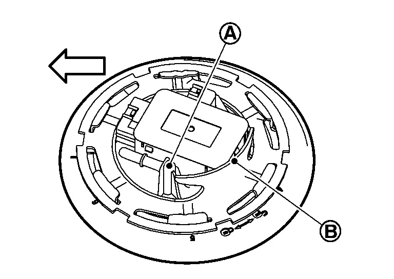
Raise fuel level sensor unit, fuel filter and fuel pump assembly.
CAUTION:
-
Never bend float arm during removal.
-
Never pollute the inside by residue fuel. Draw out avoiding inclination by supporting with a cloth.
-
Never cause impacts such by dropping when handling components.
Separate fuel tube as per the following steps to remove fuel level sensor unit, fuel filter and fuel pump assembly.
-
Disconnect harness connector (A).
-
Pinch quick connector (A) square-part with your fingers, and pull out the quick connector by hand.
-
If quick connector and tube on sender unit are stuck, push several times until they move, and pull out.
NOTE:
When separating the fuel tube, tie a gasoline-resistance rope to the tip of the fuel tube and leave the rope on the fuel tank side to easily pull the fuel tube for installation.
Sub Fuel Level Sensor Assembly
Remove lock ring from sub fuel level sensor assembly using Tool (A).
| Tool number (A) |
: (NI-45747) (shown) : KV101207S0 |
|
: Front |
Remove sub fuel level sensor assembly (1)
CAUTION:
-
Never disassemble a fuel tube (2) from sub fuel sensor assembly.
-
Never bend float arm during removal.
-
Never pollute the inside by residue fuel. Draw out avoiding inclination by supporting with a cloth.
-
Never cause impacts such by dropping when handling components.
NOTE:
Tie a gasoline-resistance rope to a tip of the tube. Draw and leave the rope to the fuel tank side sothat the rope can be the guide for installation.
INSTALLATION
2WD
Fuel Level Sensor Unit, Fuel Filter and Fuel Pump Assembly
Note to the following, and install in the reverse order of removal.
Install new O-ring to fuel tank without any twist.
CAUTION:
Do not reuse O-rings.
Install the fuel level sensor unit, fuel filter and fuel pump assembly on the fuel tank with the fuel level sensor unit, fuel filter and fuel pump assembly face (A) faced the shown in the figure against the arrow Nissan Ariya vehicle front.
|
: Nissan Ariya Vehicle front |
CAUTION:
-
Never allow seal packing to drop.
-
Never bend float arm during installing.
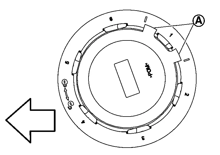
Install it so that the guard part (B) of the lock ring is at the position shown in the figure with respect to the fuel pump pipe part (A).
|
: Nissan Ariya Vehicle front |
Install lock ring for fuel level sensor, fuel filter and fuel pump assembly using Tool (A).
| Tool number (A) |
: (NI-45747) (shown) : KV101207S0 |
|
: Front |
CAUTION:
-
Install lock ring horizontally.
-
Turn the lock ring (A) until it is engaged in the fuel tank side.
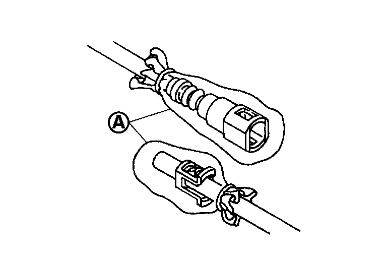
Connect quick connector of fuel feed tube as per following procedures.Check the connection for damage or any foreign materials. Align the connector with the tube, then insert the connector straight into the tube until a ÔÇťclickÔÇŁ sound is heard. After connecting, check that the connection is secured with following procedures.
-
Visually confirm that the two tabs are connected to the connector.
-
Pull (A) the tube and the connector to check that they are securely connected.
Connect harness connector.
NOTE:
Before installing inspection hole cover, check that the connecting part has no fuel leakage. Refer to Inspection.
Install inspection hole covers with the front mark (arrow) facing front of vehicle.
Lock clips by turning counterclockwise.
AWD
Sub Fuel Level Sensor Assembly
Note to the following, and install in the reverse order of removal.
Install new O-ring to fuel tank without any twist.
CAUTION:
Do not reuse O-rings.
Using the rope left on the fuel tank side at removal, run the fuel tube inside the fuel tank to install the sub fuel level sensor assembly to the fuel tank.
CAUTION:
-
Never bend float arm during installation.
-
To install, fuel tube (1) must run to the front (
) of the Nissan Ariya vehicle to avoid the interference with the float arm (2), as shown in the figure.
Install the sub fuel level sensor assembly on the fuel tank with the fuel level sensor unit, fuel filter and fuel pump assembly face (A) faced the shown in the figure against the arrow Nissan Ariya vehicle front.
|
: Nissan Ariya Vehicle front |
CAUTION:
-
Never allow seal packing to drop.
-
Never bend float arm during installing.
Install lock ring for sub fuel level sensor assembly using Tool (A).
| Tool number (A) |
: (NI-45747) (shown) : KV101207S0 |
|
: Front |
CAUTION:
-
Install lock ring horizontally.
-
Turn the lock ring (A) until it is engaged in the fuel tank side. .
Fuel Level Sensor Unit, Fuel Filter and Fuel Pump Assembly
Install new O-ring to fuel tank without any twist.
CAUTION:
Do not reuse O-rings.
Connect the fuel tube as per the following steps.
-
Insert the quick connector (A) straight to the fuel level sensor unit, fuel filter and fuel pump assembly.
-
Judge a good fit from connecting sound and tactile feedback.
-
Pull the fuel tube by hand to check a secure fit.
Connect harness connector (A).
Install the fuel level sensor unit, fuel filter and fuel pump assembly on the fuel tank with the fuel level sensor unit, fuel filter and fuel pump assembly face (A) faced the shown in the figure against the arrow Nissan Ariya vehicle front.
|
: Nissan Ariya Vehicle front |
CAUTION:
-
Never allow seal packing to drop.
-
Never bend float arm during installing.
-
To install, fuel tube (1) must run to the front (
) of the Nissan Ariya vehicle to avoid the interference with the float arm (2), as shown in the figure.
Install it so that the guard part (B) of the lock ring is at the position shown in the figure with respect to the fuel pump pipe part (A).
|
: Nissan Ariya Vehicle front |
Install lock ring for fuel level sensor unit, fuel filter and fuel pump assembly using Tool (A).
| Tool number (A) |
: (NI-45747) (shown) : KV101207S0 |
|
: Front |
CAUTION:
-
Install lock ring horizontally.
-
Turn the lock ring (A) until it is engaged in the fuel tank side.
Connect quick connector of fuel feed tube as per following procedures.Check the connection for damage or any foreign materials. Align the connector with the tube, then insert the connector straight into the tube until a ÔÇťclickÔÇŁ sound is heard. After connecting, check that the connection is secured with following procedures.
-
Visually confirm that the two tabs are connected to the connector.
-
Pull (A) the tube and the connector to check that they are securely connected.
Connect harness connector.
Inspection Hole Cover
-
Before installing inspection hole cover, check that the connecting part has no fuel leakage. Refer to Inspection.
Install inspection hole covers with the front mark (arrow) facing front of vehicle.
Lock clips by turning counterclockwise.
Disassembly and Assembly
Disassembly
2WD
NOTE:
Before disassembly, note the proper placement of the wires to the correct terminals and correct wire routing to the terminals.
Disconnect fuel level sensor unit and fuel tank temperature sensor harness connectors  .
.
Remove wires from wire clips  .
.
CAUTION:
Be careful not to damage wires when removing them from wire clips.
Release tab using suitable tool, then slide fuel level sensor unit in direction.
Inspection
INSPECTION AFTER INSTALLATION
Use the following procedure to check for fuel leakage.
Place the ignition switch in the ÔÇťONÔÇŁ position (with engine stopped), then check connections for leakage by applying fuel pressure to fuel piping.
Start engine. Then let it idle and check that there is no fuel leakage at the fuel system connections.
Fuel Tank
Exploded View
2WD
|
Fuel tank | |
Fuel tank band (RH) | |
Fuel tank band (LH) |
|
Clamp | |
Fuel filler hose | |
Fuel filler tube |
|
Comply with the assembly procedure when tightening. Refer to Removal and Installation | ||||
 |
: N┬Ěm (kg-m, ft-lb) | ||||
 |
: N┬Ěm (kg-m, in-lb) | ||||
 , ,  : Indicates that the parts is connected at points with same symbols in actual Nissan Ariya vehicle. : Indicates that the parts is connected at points with same symbols in actual Nissan Ariya vehicle. |
|||||
AWD
|
Fuel tank | |
Fuel tank band (RH) | |
Fuel tank band (LH) |
|
Clamp | |
Fuel filler hose | |
Fuel filler tube |
|
Comply with the assembly procedure when tightening. Refer to Removal and Installation | ||||
|
: N┬Ěm (kg-m, ft-lb) | ||||
|
: N┬Ěm (kg-m, in-lb) | ||||
| , : Indicates that the parts is connected at points with same symbols in actual Nissan Ariya vehicle. |
|||||
Removal and Installation
REMOVAL
WARNING:
Be sure to read ÔÇťGeneral PrecautionsÔÇŁ when working on the fuel system. Refer to General Precautions .
Perform the steps 1 to 7 of ÔÇťREMOVALÔÇŁ in ÔÇť FUEL LEVEL SENSOR UNIT, FUEL FILTER AND FUEL PUMP ASSEMBLYÔÇŁ. Refer to Removal and Installation.
Drain fuel from fuel tank if necessary. Refer to Removal and Installation.
CAUTION:
-
Because fuel tank forwardly inclines and becomes unstable when installing/removing, fuel should be drained if found the remaining quantity.
-
Situate Nissan Ariya vehicle on a flat and solid surface.
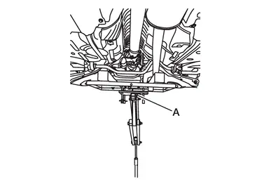
Remove main muffler. Refer to Removal and Installation.
Remove rear propeller shaft. (AWD models) Refer to Removal and Installation.
Remove under cover LH and under cover RH.
Disconnect EVAP tube  from EVAP canister.
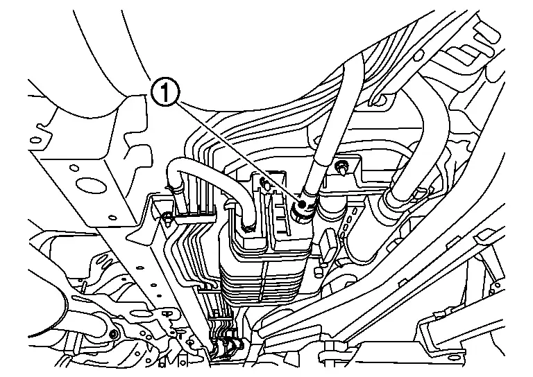
Remove fuel filler hose at fuel filler tube side.
 |
: Nissan Ariya Vehicle front |
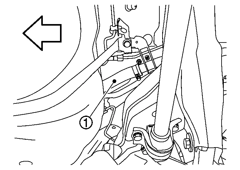
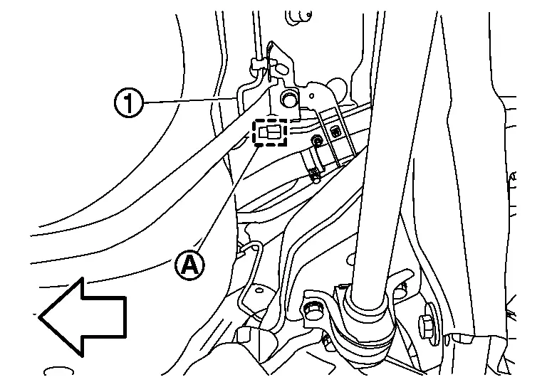
Support center of fuel tank with suitable jack .
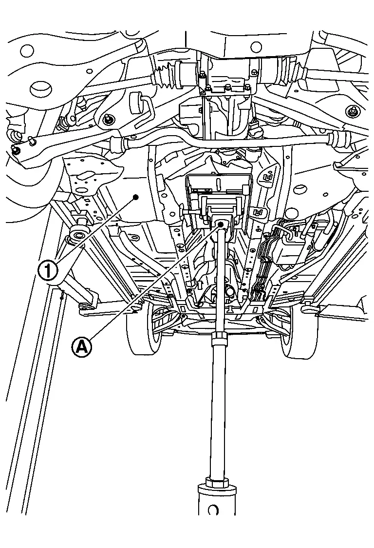
Remove fuel tank bands.
Tilt the fuel tank forward and lower the fuel tank front 10 cm (3.94 in).
Disconnect vent hose at rear side of fuel tank.
-
Instruction for quick connector
of EVAP tube. Refer to Quick Connector.: Nissan Ariya Vehicle front
Lower suitable jack carefully to remove fuel tank while holding it by hand.
CAUTION:
Fuel tank may be in an unstable condition, due to the shape of the fuel tank bottom. Be sure to secure tank at all times.
If replacing the fuel tank, remove the fuel level sensor unit, fuel filter and fuel pump assembly to transfer to the new fuel tank. Remove and discard the O-ring. Refer to Removal and Installation.
INSTALLATION
Installation is in the reverse order of removal.
Fuel Filler Hose
-
Insert fuel filler hose to the length below.
35 mm (1.38 in) -
Be sure hose clamp is not placed on swelled area of fuel filler tube.
-
Tighten the clamp hand with the top mark
until the mark is on the bolt head flange.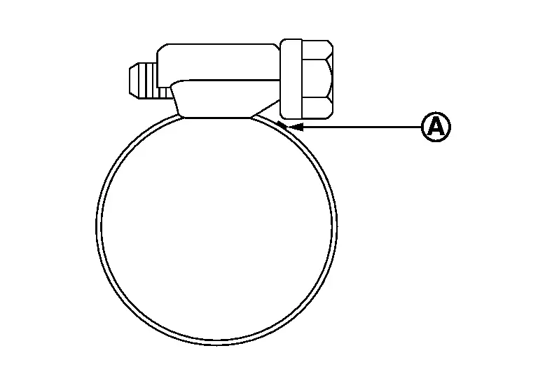
Fuel Filler Tube
-
When installing the fuel filler tube, make sure that the lip
of the fuel filler base is firmly attached to the rib of the cap less unit part.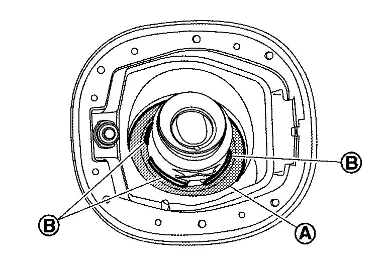
Inspection
INSPECTION AFTER INSTALLATION
Use the following procedure to check for fuel leakage.
Place the ignition switch in the ÔÇťONÔÇŁ position (with engine stopped), then check connections for leakage by applying fuel pressure to fuel piping.
Start engine. Then let it idle and check that there is no fuel leakage at the fuel system connections.
Fuel Filler Tube
Removal and Installation
REMOVAL
WARNING:
Be sure to read ÔÇťGeneral PrecautionsÔÇŁ when working on the fuel system. Refer to General Precautions.
Remove rear wheel housing protector. Refer to Removal and Installation.
Remove and reposition rear brake caliper assembly. Refer to Removal and Installation.
Remove brake hose locking plates (A) from rear knuckle.
Remove rear shock absorber. Refer to Removal and Installation.
Remove rear coil spring. Refer to Removal and Installation.
Remove main muffler system. Refer to Removal and Installation.
Disconnect EVAP tube (A) from fitting (1) and (2), Disconnect fuel filler hose clamp (B) from fuel filler hose (3) to fuel filler tube (4).
-
Instruction for quick connector of EVAP tube. Refer to Quick Connector.
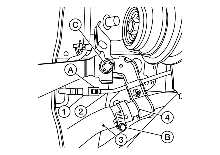
Using a suitable jack support the fuel tank and remove fuel tank band bolt (C).
CAUTION:
Fuel tank may be in an unstable condition, due to the shape of the fuel tank bottom. Be sure to secure tank at all times.
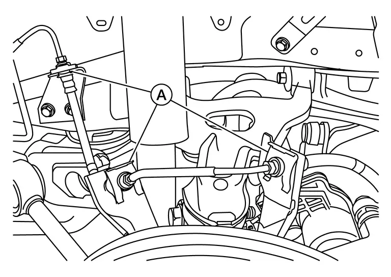
Remove upper fuel filler tube bolt (A).

Remove lower fuel filler tube bolt (A).
Set a suitable jack under the rear suspension member (A).
Remove bolts from right side of rear suspension member.
Partially loosen suspension member bolts on LH side.
Partially lower suspension member.
Remove fuel filer tube.
INSTALLATION
Installation is in the reverse order of removal.
Fuel Filler Hose
-
Insert fuel filler hose to the length below.
35 mm (1.38 in) -
Be sure hose clamp is not placed on swelled area of fuel filler tube.
-
Tighten the clamp hand with the top mark (A) until the mark is on the bolt head flange.
Fuel Filler Tube
-
When installing the fuel filler tube, make sure that the lip (A) of the fuel filler base is firmly attached to the rib (B) of the cap less unit part.
Evap Canister
Hydraulic Layout
HYDRAULIC LAYOUT
2WD
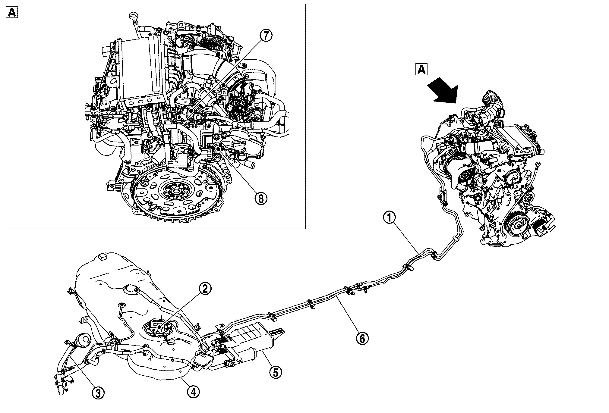
| 1. | EVAP line (EVAP canister to EVAP canister purge volume control solenoid valve) | 2. | Fuel level sensor unit, fuel filter and fuel pump assembly | 3. | Fuel filler tube |
| 4. | Fuel tank | 5. | EVAP canister | 6. | Fuel feed line |
| 7. | High pressure fuel pump | 8. | EVAP canister purge volume control solenoid valve | ÔÇö | ÔÇö |
CAUTION:
Do not use soapy water or any type of solvent while installing vacuum hose or purge hoses.
AWD
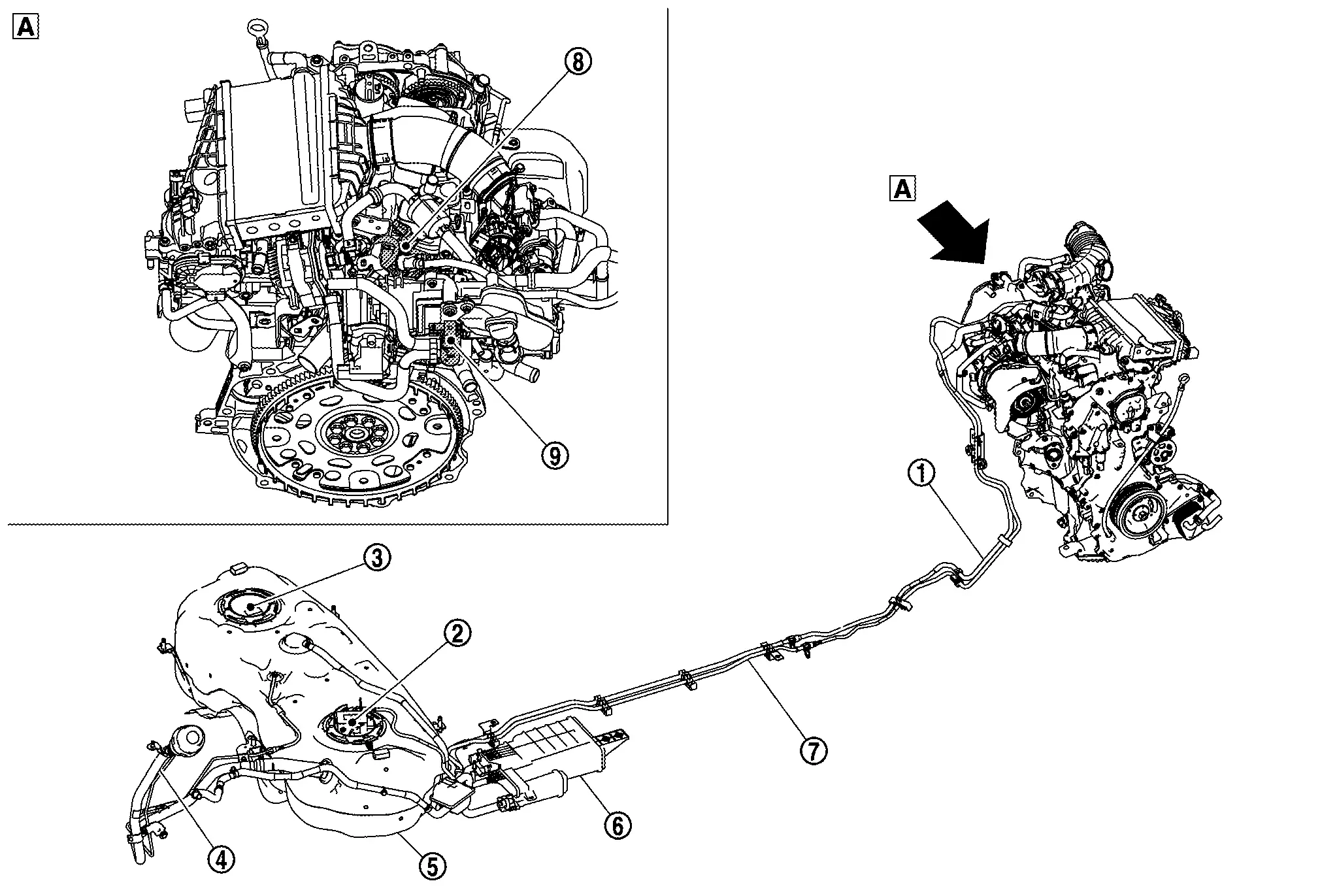
| 1. | EVAP line (EVAP canister to EVAP canister purge volume control solenoid valve) | 2. | Fuel level sensor unit, fuel filter and fuel pump assembly | 3. | Sub fuel level sensor assembly |
| 4. | Fuel filler tube | 5. | Fuel tank | 6. | EVAP canister |
| 7. | Fuel feed line | 8. | High pressure fuel pump | 9. | EVAP canister purge volume control solenoid valve |
CAUTION:
Do not use soapy water or any type of solvent while installing vacuum hose or purge hoses.
DISASSEMBLY
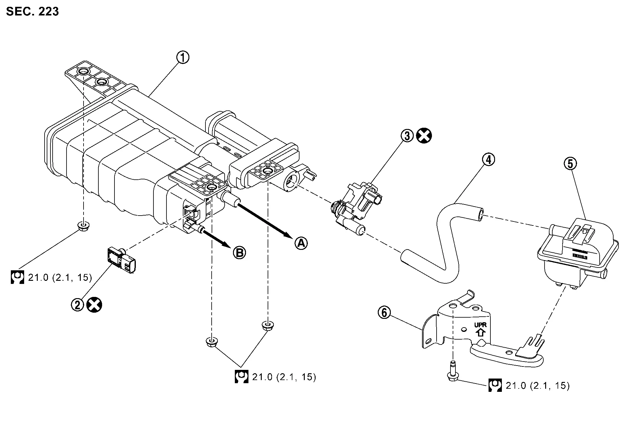
| 1. | EVAP canister | 2. | EVAP canister control pressure sensor | 3. | EVAP canister vent control valve |
| 4. | EVAP canister vent control valve hose | 5. | EVAP canister filter | 6. | EVAP canister filter bracket |
| A. | To fuel tank. Exploded View | B. | To vacuum delay valve assembly. Exploded View | ÔÇö | ÔÇö |
|
: N┬Ěm (kg-m, ft-lb) | ÔÇö | ÔÇö | ÔÇö | ÔÇö |
|
: Always replace after every disassembly. | ||||
Removal and Installation
NOTE:
The EVAP canister vent control valve and EVAP canister control pressure sensor can be removed without removing the EVAP canister.
REMOVAL
Remove under cover RH (1).
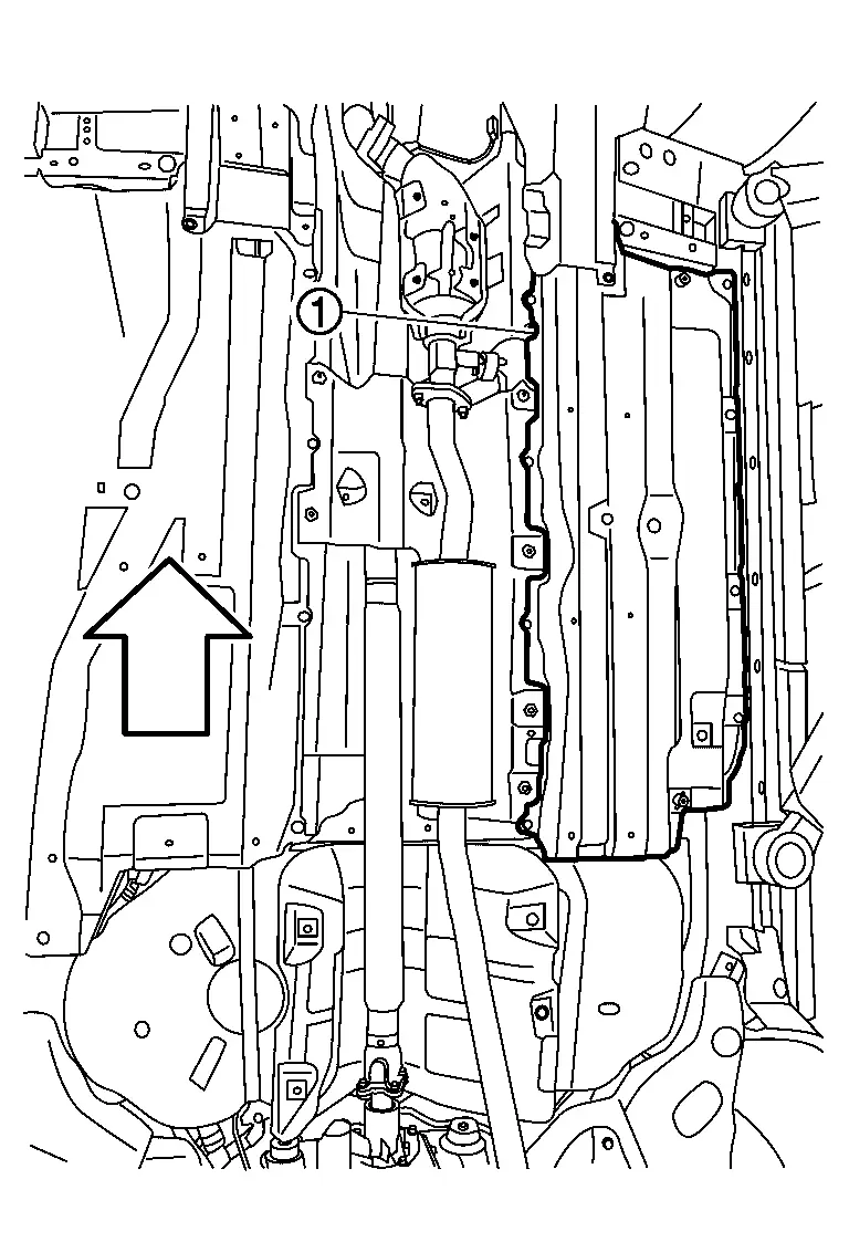
|
: Nissan Ariya Vehicle front |
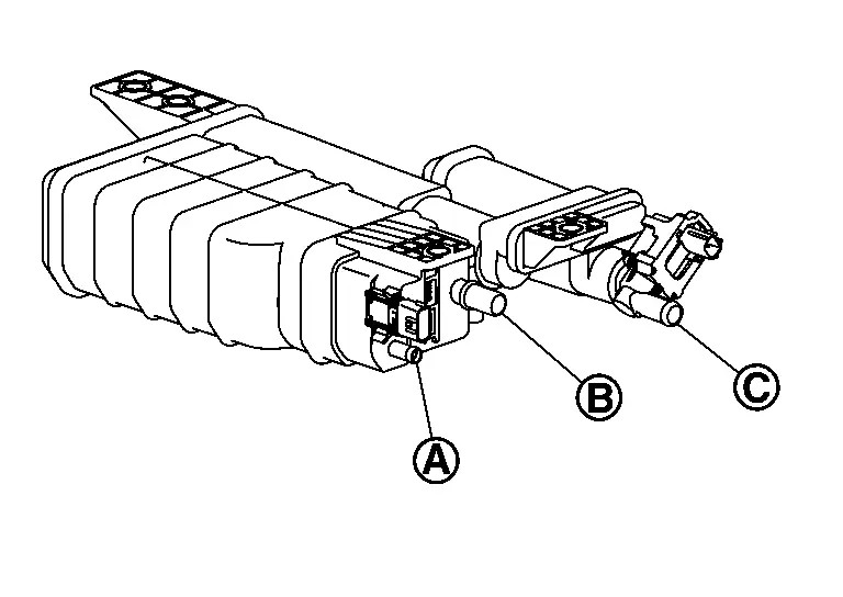
Disconnect the harness connector from EVAP canister control pressure sensor and the EVAP canister vent control valve.
Disconnect the EVAP canister purge hose, the EVAP canister vent line, and the EVAP canister vent control valve hose.
Remove the EVAP canister bolt.
Remove the EVAP canister from the Nissan Ariya vehicle.
Remove the following from the EVAP canister (if necessary).
-
EVAP canister control pressure sensor.
-
EVAP canister vent control valve.
INSTALLATION
Installation is in the reverse order of removal.
Install the EVAP canister then tighten the nuts to specification in sequence
| EVAP canister nuts | : 21 Nm (2.1 kg-m, 15 ft-lb) |
Inspection
Check EVAP canister as follows.
Block port .
Blow air into port and check that it flows freely out of port  .
.
Release blocked port .
Apply vacuum pressure to port and check that vacuum pressure exists at the ports and .
Block port and .
Apply pressure to port and check that there is no leakage.
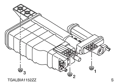
Evap Canister Filter
Exploded View
|
EVAP canister | |
EVAP canister control pressure sensor | |
EVAP canister vent control valve |
|
EVAP canister vent control valve hose | |
EVAP canister filter | |
EVAP canister filter bracket |
|
To fuel tank. Exploded View. | |
To vacuum delay valve assembly. Exploded View. | ||
|
: N┬Ěm (kg-m, ft-lb) | ||||
|
: Always replace after every disassembly. | ||||
Removal and Installation
REMOVAL
Disconnect EVAP canister vent control valve hose from EVAP canister filter.
Disconnect EVAP canister drain hose from EVAP canister filter.
Remove the bolt and the EVAP canister filter.
INSTALLATION
Installation is in the reverse order of removal.
Other materials:
Preparation. Always Replace with New Parts
Always Replace with New Parts
Always Replace with New PartsNever Reuse These PartsPart CodeFor additional information:
Combination switch
25540M
SPIRAL CABLE EXPLODED VIEW
Passenger air bag module bolt
-
PASSENGER AIR BAG MODULE EXPLODED VIEW
Passenger air bag module screw
-
PASSENGER ...
Manual Air Conditioning. Precaution. Precautions
Precautions
Precaution for Supplemental Restraint System (SRS) "AIR BAG" and "SEAT BELT PRE-TENSIONER"
The Supplemental Restraint System such as ÔÇťAIR BAGÔÇŁ and ÔÇťSEAT BELT
PRE-TENSIONERÔÇŁ, used along with a front seat belt, helps to reduce the
risk or severity of injury to the driver and ...
Symptom Diagnosis. Srs Air Bag Warning Lamp Does Not Turn on
Diagnosis Procedure
CHECK DTC WITH AIR BAG DIAGNOSIS SENSOR UNIT
Check that DTC is not detected with air bag diagnosis sensor unit.
Is the inspection result normal?
YES>>
GO TO 2.
NO>>
Refer to DTC Index.
CHECK DTC WITH COMBINATION METER
Check that DTC is not detected with com ...