Nissan Rogue (T33) 2021-Present Service Manual: Kr15ddt :: Periodic Maintenance
Air Cleaner Filter
Exploded View
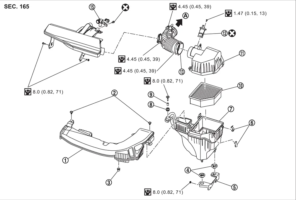
| 1. | Air duct (Inlet) | 2. | Clip | 3. | Mounting rubber |
| 4. | Mounting rubber | 5. | Bracket | 6. | Clip |
| 7. | Air cleaner body | 8. | Mounting rubber | 9. | Collar |
| 10. | Air cleaner filter | 11. | Air cleaner cover | 12. | Mass air flow sensor |
| 13. | Air duct | 14. | Resonator | 15. | Crankcase Vent Actuator |
| A | To admission valve. Refer to Exploded View. | â | â | â | â |
 |
: N·m (kg-m, in-lb) | ||||
 |
: Always replace after every disassembly. | ||||
Removal and Installation
REMOVAL
Remove the air duct from the air cleaner cover.
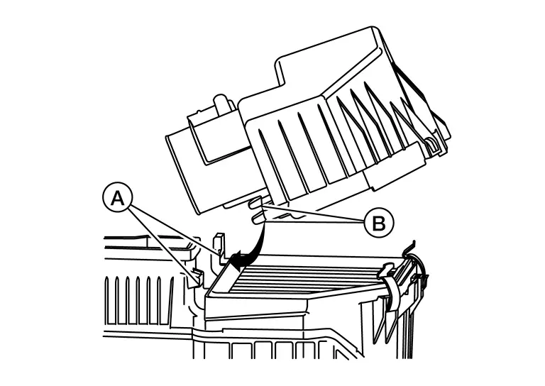
Release the clips (A) of air cleaner cover (1).
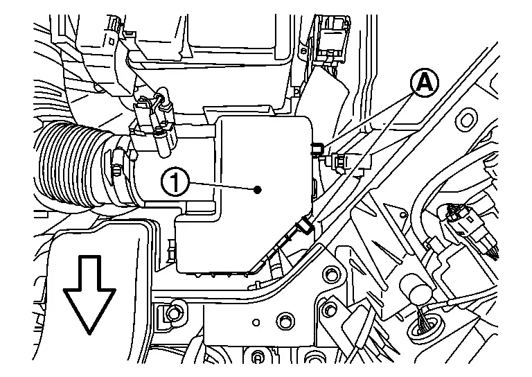
| : Nissan Ariya Vehicle front |
Remove air cleaner filter.
INSTALLATION
Install the air cleaner filter.
Install the air cleaner cover tabs (B) at approximately a 45 degree angle into air cleaner body hinge (A).
Press air cleaner cover onto air cleaner body and latch clips.
 NOTE:
NOTE:
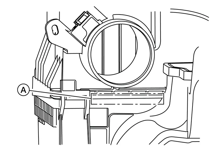
Verify the rubber seal is not visible in the area shown (A). If the rubber seal is visible, remove and reinstall air cleaner cover.
Attach the air duct to the air cleaner cover.
Inspection (Dry Paper Type)
INSPECTION AFTER REMOVAL
Examine with eyes that there is no stain, clogging, or damage on air cleaner element.
-
Remove dusts (such as dead leafs) on air cleaner element surface and inside cleaner case.
-
To clean air cleaner element, blow it from intake manifold side towards air intake side to remove trash or dust.
-
If clogging or damage is observed, replace the air cleaner element.
MAINTENANCE INTERVAL
Refer to Periodic Maintenance.
Drive Belt
With Idle Start/stop System
Exploded View
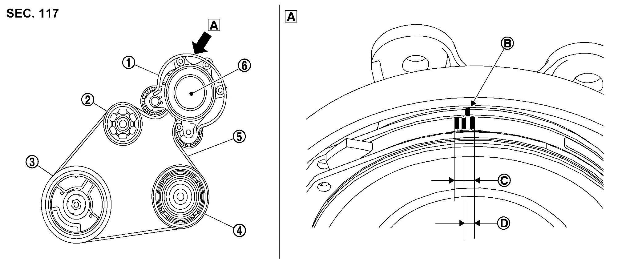
| 1. | Drive belt auto-tensioner | 2. | Water pump | 3. | Crankshaft pulley |
| 4. | A/C compressor | 5. | Drive belt | 6. | Sub starter & generator |
| A | View A | B | Indicator (notch on the fixed side) | C | Possible use range |
| D | Range when new drive belt is installed | â | â | â | â |
Removal and Installation
REMOVAL
Remove drive belt auto-tensioner. Refer toRemoval and Installation.
-
Keep each auto-tensioner pulley arm locked after drive belts are removed.
Remove the drive belt.
-
Keep each drive belt auto-tensioner pulley arm locked after drive belts are removed.
INSTALLATION
-
Installation is in the reverse order of removal.
Inspection
 |
Drive belt auto-tensioner |  |
Water pump |  |
Crankshaft pulley |
 |
A/C compressor |  |
Drive belt |  |
Sub starter & generator |
 |
View A | B | Indicator (notch on the fixed side) | C | Possible use range |
 |
Range when new drive belt is installed |
WARNING:
Perform this step when engine is stopped.
-
Check that the indicator [notch on fixed side
 ] of drive belt auto-tensioner is within the possible use range (C) shown.NOTE:
-
Check drive belt auto-tensioner indication when the engine is cold.
-
When new drive belt is installed, the indicator (notch on fixed side) should be within range in the figure.
-
-
Visually check entire drive belt for wear, damage or cracks.
-
If the indicator (notch on fixed side) is out of the possible use range or belt is damaged, replace drive belt.
Adjustment
Drive belt tension is not manually adjusted. It is automatically adjusted by the drive belt auto-tensioner.
Spark Plug
Exploded View
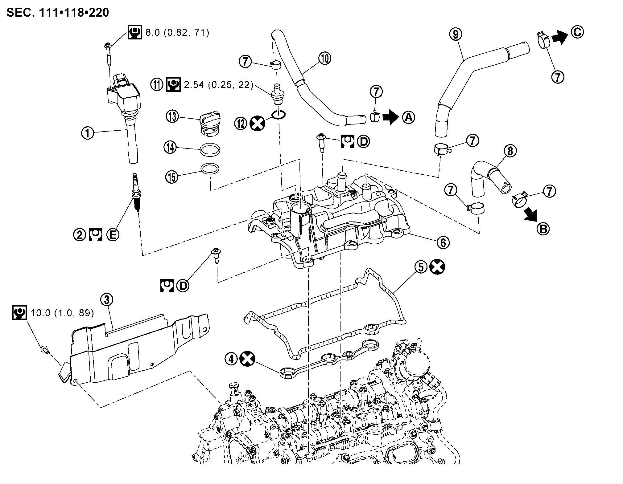
 |
Ignition coil | |
Spark plug | |
Cover (right) |
|
Rocker cover gasket | |
Rocker cover gasket | |
Rocker cover |
 |
Clamp |  |
Resonator hose |  |
Turbo hose |
 |
Blow-by hose |  |
PCV valve |  |
O-ring |
 |
Oil filler cap |  |
Oil filler gasket 1 |  |
Oil filler gasket 2 |
|
To Intake manifold. Refer to Exploded View. | |
To Resonator. Refer to Exploded View. |  |
To Air duct. Refer to Exploded View. |
|
Comply with the installation procedure when tightening. Refer to Removal and Installation. |  |
Comply with the installation procedure when tightening. Refer to Removal and Installation. | ||
 |
: N·m (kg-m, ft-lb) | ||||
|
: N·m (kg-m, in-lb) | ||||
|
: Always replace after every disassembly. | ||||
Removal and Installation
REMOVAL
Remove engine cover. Refer to Removal and Installation.
Disconnect air inlet hose. Refer to Removal and Installation.
Remove turbo hose.
Remove ignition coil. Refer to Removal and Installation.
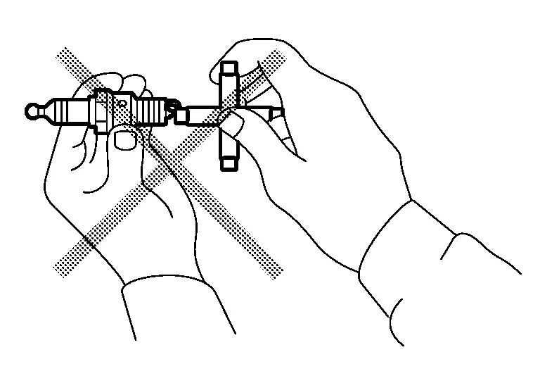
Remove spark plug with spark plug wrench (commercial service tool).
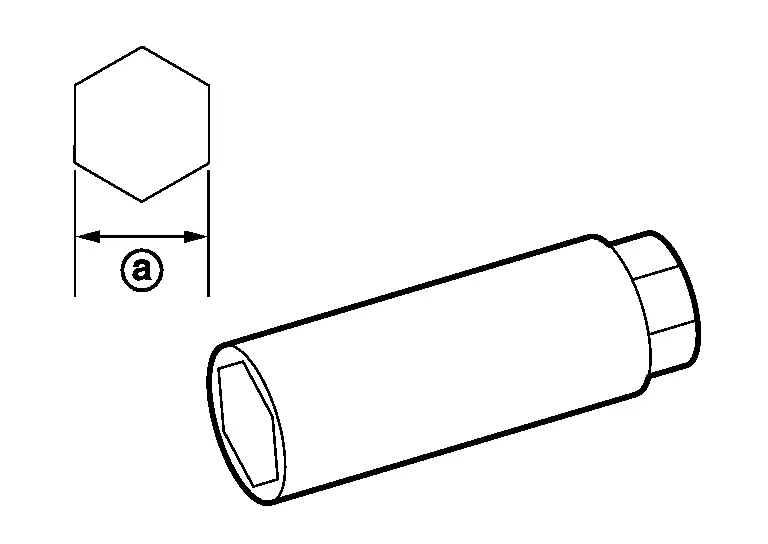
 |
: 14 mm (0.55 in) |
CAUTION:
-
Never drop or shock spark plug.
-
Never disassemble ignition coil.
After removal, inspect the spark plug. Refer to Inspection.
INSTALLATION
Note the following, and install in the reverse order of removal.
-
Install spark plug with spark plug wrench (commercial service tool).
Spark plug : 12.5 N·m (1.3 kg-m, 9 ft-lb) NOTE:
The position of the ground electrode on the genuine spark plugs is adjusted to be in the position with the most favorable ignitability when tightened to the specified torque. When replacing the spark plugs, the genuine spark plugs with the adjusted ground electrode position are recommended.
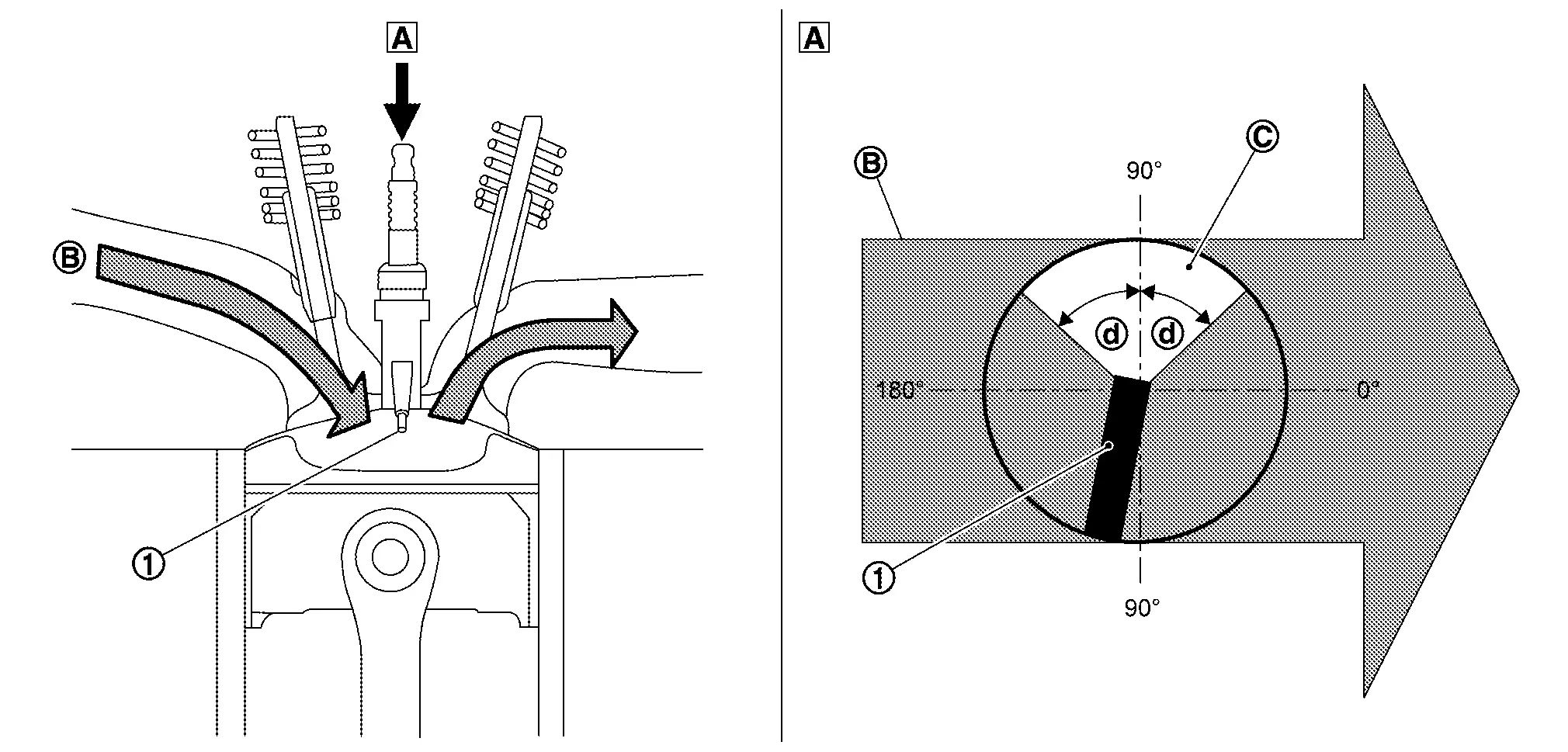
Ground electrode Air fuel mixture flow Fuel efficiency performance range 
45°
Inspection
Use the standard type spark plug for normal condition.
| Spark plug (Standard type) | : Refer to Spark Plug. |
CAUTION:
-
Do not drop or shock spark plug.
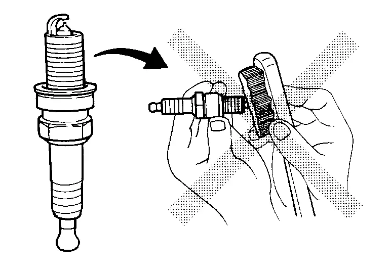
-
Do not use a wire brush for cleaning.
-
If spark plug tip is covered with carbon, spark plug cleaner may be used.
| Cleaner air pressure | : Less than 588 kPa (5.9 bar, 6 kg/cm2, 85 psi) |
| Cleaning time | : Less than 20 seconds |
-
Checking and adjusting spark plug gap is not required between replacement intervals.
Measure spark plug gap.
When it exceeds the limit, replace spark plug, even if it is within the specified replacement mileage. Refer to Spark Plug.
Other materials:
P0053 A/f Sensor 1 Heater
DTC Description
DTC DETECTION LOGIC DTC
CONSULT screen terms
(Trouble diagnosis content)
DTC detection condition
P0053
00
HO2S1 HTR B1
(HO2S heater resistance bank 1 sensor 1)
Diagnosis condition
â
Signal (terminal)
A/F sensor 1 heater signal
Threshold
D ...
Ãtiquette des pneus
Exemple
Informations de base
La lÃĐgislation fÃĐdÃĐrale impose aux fabricants de pneus dâapposer sur le flanc de chaque pneu des informations normalisÃĐes et clairement lisibles. Ces marquages, prÃĐsents sur les pneus du Nissan Rogue, permettent dâidentifier les caractÃĐristiques essenti ...
U0402 Can Communication
DTC Description
DTC DETECTION LOGIC DTC
CONSULT screen terms
(Trouble diagnosis content)
DTC detection condition
U0402
00
Invalid data (TCM)
(Invalid Data Received From TCM)
Diagnosis condition
Ignition switch ON
Signal (terminal)
â
Threshold
When ECM is ...