Nissan Rogue (T33) 2021-Present Service Manual: Kr15ddt :: Basic Inspection
Camshaft Valve Clearance
Inspection and Adjustment
INSPECTION
Perform inspection as follows after removal, installation or replacement of camshaft or valve-related parts, or if there is unusual engine conditions regarding valve clearance.
-
Remove rocker cover. Refer to Removal and Installation.
-
Measure the valve clearance with the following procedure:
-
Set No. 1 cylinder at TDC of its compression stroke.
-
Rotate crankshaft pulley
 clockwise and align TDC mark (no paint)
  to timing indicator
  on front cover.
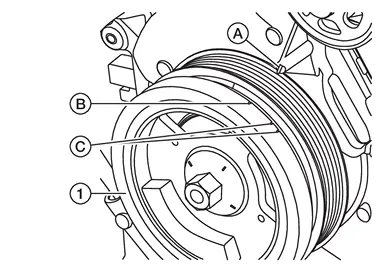
(C) : Paint marks (Not used for service) -
At the same time, check that both intake and exhaust cam noses of No. 1 cylinder face inside (
 ) as shown in the figure.
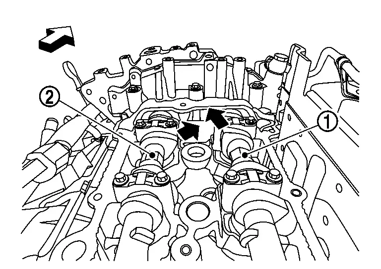

: Camshaft (EXH) 
: Camshaft (INT) 
: Engine front -
If they do not face inside, rotate crankshaft pulley once more (360 degrees) and align as shown in the figure.
-
-
Use a feeler gauge, measure the clearance between valve lifter and camshaft.
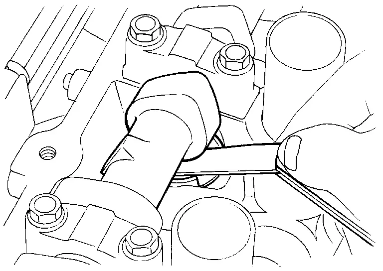
Valve clearance : Refer to Camshaft. -
By referring to the figure, measure the valve clearances at locations marked âÃâ as shown in the table below [locations indicated with black arrow (
) in the figure] with a feeler gauge.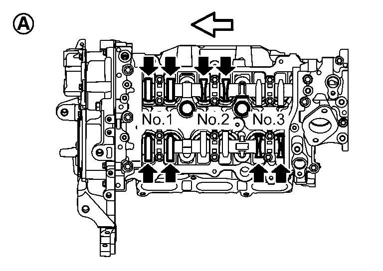
: No. 1 cylinder at compression TDC : Engine front Measuring position No. 1 CYL. No. 2 CYL. No. 3 CYL. No. 1 cylinder at compression TDC EXH Ã Ã INT Ã Ã
-
-
Set No. 3 cylinder at TDC of its compression stroke.
-
Rotate crankshaft pulley (480 degrees).
CAUTION:
Do not rotate crankshaft pulley counterclockwise. In case of excess rotate, set the No.1 cylinder at TDC of its compression stroke, and turn it 480 degrees clockwise.
-
By referring to the figure, measure the valve clearance at locations marked âÃâ as shown in the table below [locations indicated with black arrow (
) in the figure] with a feeler gauge.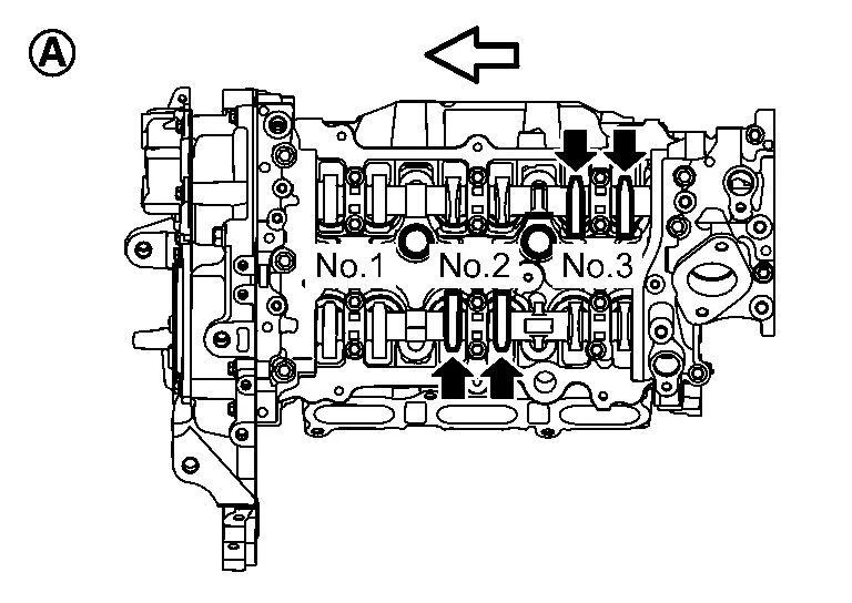
: No. 3 cylinder at compression TDC : Engine front Measuring position No. 1 CYL. No. 2 CYL. No. 3 CYL. No. 3 cylinder at compression TDC EXH Ã INT Ã
-
-
-
If out of standard, perform adjustment.
ADJUSTMENT
-
Perform adjustment depending on selected head thickness of valve lifter.
-
Remove camshaft. Refer to Removal and Installation.
-
Remove valve lifters at the locations that are out of the standard.
-
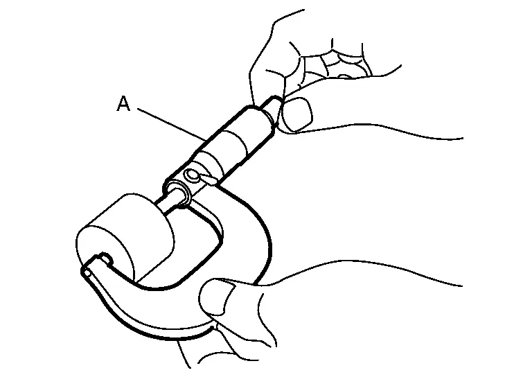
Measure the center thickness of the removed valve lifters with a suitable tool (A).
-
Use the equation below to calculate valve lifter thickness for replacement.
Valve lifter thickness calculation: t = t1 + (C1 â C2) t = Valve lifter thickness to be replaced t1 = Removed valve lifter thickness C1 = Measured valve clearance C2 = Standard valve clearance: Intake : 0.32 mm (0.0126 in) Exhaust : 0.31 mm (0.0122 in) -
Thickness of new valve lifter (B) can be identified by stamp mark
on the reverse side (inside the cylinder).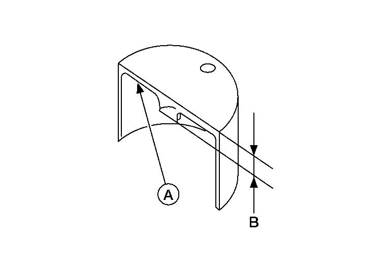
-
Stamp mark â302â indicates 3.02 mm (0.1189 in) in thickness.
 NOTE:
NOTE:
Available thickness of valve lifter: 26 sizes range 3.00 to 3.50 mm (0.1181 to 0.1378 in) in steps of 0.02 mm (0.0008 in) (when manufactured at factory). Refer to Camshaft.
-
-
Install the selected valve lifter.
-
Install camshaft. Refer to Removal and Installation.
-
Install timing chain and related parts. Refer to Removal and Installation.
-
Manually rotate crankshaft pulley a few rotations.
-
Check that the valve clearance is within the standard. Refer to Inspection.
-
Installation of the remaining parts is in the reverse order of removal.
-
Warm up the engine, and check for unusual noise and vibration.
Compression Pressure
Inspection
-
Warm up engine thoroughly. Then, stop it.
-
Release fuel pressure. Refer to Work Procedure.
-
Disconnect fuel pump fuse to avoid fuel injection during measurement. Refer to How To Check.
-
Remove ignition coil and spark plug from each cylinder. Refer to Removal and Installation.
-
Connect engine tachometer (not required in use of CONSULT).
-
Install compression tester (A) with adapter onto spark plug hole.
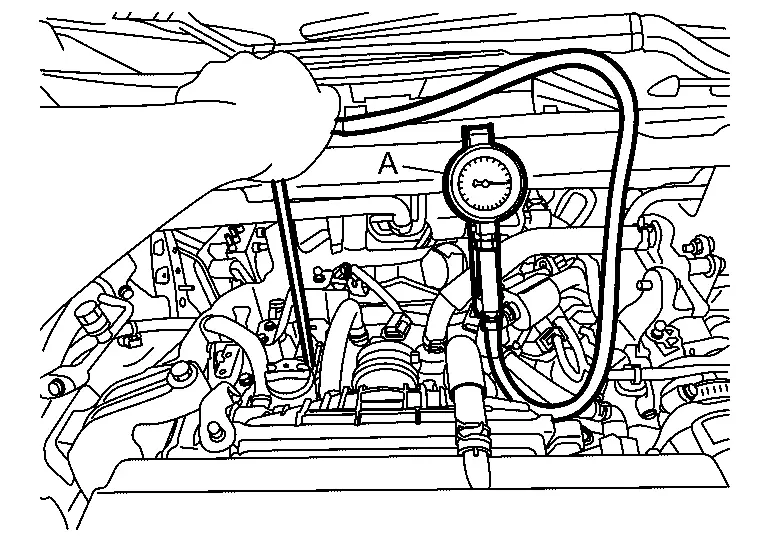
-
Use compression tester whose end
 (rubber portion) is smaller than 20 mm (0.79 in) in diameter.
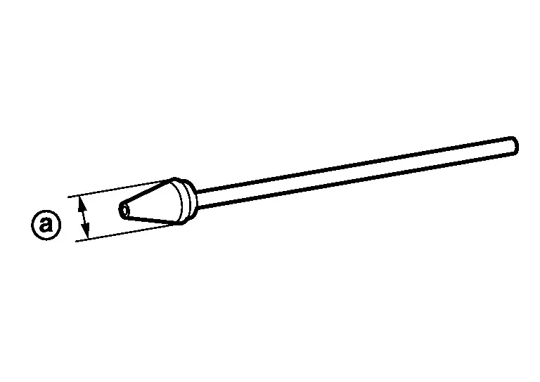
-
-
With accelerator pedal fully depressed, turn ignition switch to âSTARTâ for cranking. When the gauge pointer stabilizes, read the compression pressure and engine rpm. Perform these steps to check each cylinder.
Compression pressure : Refer to General Specification. CAUTION:
Always use a fully charged battery to obtain specified engine speed.
-
If the engine speed is out of specified range, check battery liquid for proper gravity. Check engine speed again with normal battery gravity.
-
If compression pressure is below minimum value, check valve clearances and parts associated with combustion chamber (Valve, valve seat, piston, piston ring, cylinder bore, cylinder head, cylinder head gasket). After the checking, measure the compression pressure again.
If some cylinder has low compression pressure, pour small amount of engine oil into the spark plug hole of the cylinder to re-check it for compression.
-
If the added engine oil improves the compression, piston rings may be worn out or damaged. Check piston rings and replace if necessary.
-
If the compression pressure remains at low level despite the addition of engine oil, valves may be malfunctioning. Check valves for damage. Replace valve or valve seat accordingly.
-
-
If two adjacent cylinders have respectively low compression pressure and their compression remains low even after the addition of engine oil, gaskets are leaking. In such a case, replace cylinder head gaskets.
-
-
After inspection is completed, install removed parts.
-
Start engine, and confirm that engine runs smoothly.
-
Perform trouble diagnosis. If DTC appears, erase it. Refer to Description.
Other materials:
P2615 Intake Camshaft Position Sensor
DTC Description
DTC DETECTION LOGIC DTC
CONSULT screen terms
(Trouble diagnosis content)
DTC detection condition
P2615
00
A camshaft posi signal B1
(Camshaft A Position Signal Output Circuit Low Bank 1)
Diagnosis condition
Engine running at idle
Signal (terminal)
...
Poste de conduite
Cette vue dâensemble du poste de conduite du Nissan Rogue vous aide à repÃĐrer rapidement les commandes essentielles, que vous conduisiez en ville ou sur autoroute. Selon la finition de votre Nissan Rogue, certaines fonctions peuvent Être prÃĐsentes (signalÃĐes par *), notamment ProPILOT Assist ...
Dtc/circuit Diagnosis. U1327-52 Mac Key Update
DTC Description
DTC DETECTION LOGIC DTC No.
CONSULT screen items
(Trouble diagnosis content) DTC Detection Condition
U1327-52
MAC key update
(Message authentication code key update)
Diagnosis condition
-
Signal (terminal)
-
Threshold
MAC key writing is incomplete. ...