Nissan Rogue (T33) 2021-Present Service Manual: Ipdm E/r :: System Description
Component Parts
Component Parts Location
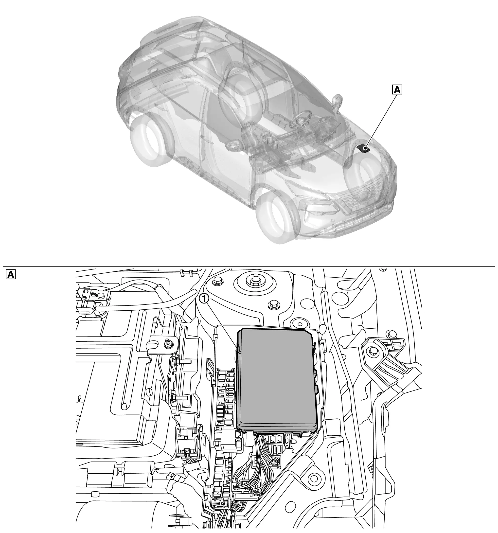
 : Front of vehicle
| A. | Engine compartment LH side |
| No. | Component | Function |
|---|---|---|
| 1. | IPDM E/R (Intelligent Power Distribution Module Engine Room) | Refer to System Description. |
System
Relay Control System
System Description
SYSTEM DIAGRAM
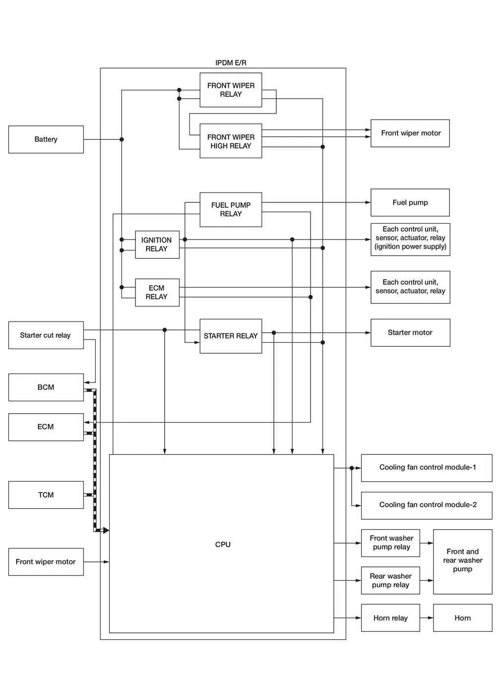
DESCRIPTION
IPDM E/R activates the internal control circuit to perform the relay ON-OFF control according to the input signals from various sensors and the request signals received from control units via CAN communication.
 NOTE:
NOTE:
To prevent to the parts, IPDM E/R integrated relays cannot be removed.
| Control relay | Input/output | Transmit unit | Control part | Reference |
|---|---|---|---|---|
|
Front wiper request signal | BCM (CAN) | Front wiper motor | System Description |
| Front wiper stop position signal | Front wiper motor | |||
| Starter relay | Ignition ON signal | BCM (CAN) | Starter motor | System Description |
| Cranking enable (ECM) signal | ECM (CAN) | |||
| Cranking enable (TCM) signal | TCM (CAN) | |||
| Ignition relay | Ignition ON signal | BCM (CAN) | Ignition power supply | System Description |
NOTE:
ECM controls the following relays:
-
ECM relay
-
Fuel pump relay
Smart Field-Effect Transistor (fet)
System Description
System Description
A Smart Field-Effect Transistor (FET) is a transistor used to monitor and control current flow on module outputs. The IPDM E/R uses a Smart FET protection strategy to prevent module damage in the event of excessive current flow. The Smart FET protection strategy monitors its outputs for excessive current, and when a fault occurs, shuts down the output and records a DTC.
COMPONENT FUNCTION WITHIN SYSTEM
-
Smart FET turns the each lamps ON according to the request from BCM.
-
Smart FET turns the A/C compressor (magnetic clutch) ON according to the request from ECM.
INDIVIDUAL COMPONENT FUNCTION
Smart FET supplies power supply voltage to the each lamp and the A/C compressor (magnetic clutch).
COMPONENT OPERATION
Smart FET, that uses MOS field effect transistor, is adopted for each lamp and A/C compressor (magnetic clutch) control.
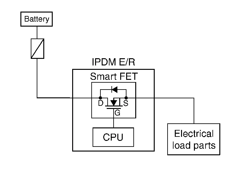
NOTE:
A MOS field effect transistor is a transistor in which the gate is composed of a metal-oxide-semiconductor (MOS). Field effect transistor is controlled by voltage, while ordinary transistor is controlled by current. Electrode of field effect transistor is called source, drain, or gate, while electrode of ordinary transistor is called emitter, collector, or base.
Power Control System
System Description
SYSTEM DIAGRAM
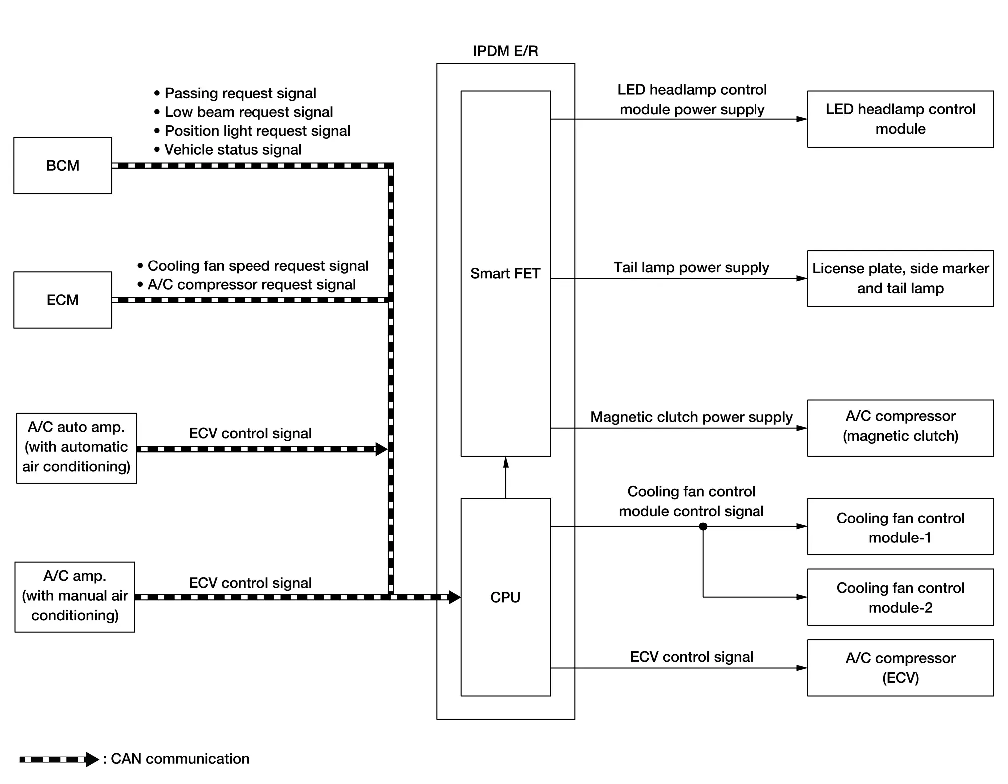
| Component | Function |
|---|---|
| BCM | BCM transmits each lamp ON/OFF request signal and Nissan Ariya vehicle status signal to the IPDM E/R via CAN communication. |
| ECM |
|
| A/C auto amp. | A/C auto amp. transmits the ECV control signal to the IPDM E/R via CAN communication. |
| A/C amp. | A/C amp. transmits the ECV control signal to the IPDM E/R via CAN communication. |
| IPDM E/R |
|
| Smart FET | Refer to System Description. |
| LED headlamp control module | IPDM E/R supplies power supply voltage to each lamp, and turns the each lamp ON. |
| Parking lamp, license plate lamp, side marker lamp and tail lamp | |
| A/C compressor (magnetic clutch) | IPDM E/R supplies power supply voltage to the A/C compressor (magnetic clutch), and turns the magnetic clutch ON. |
|
IPDM E/R controls each actuator. |
| A/C compressor (ECV) |
SIGNAL TRANSMISSION FUNCTION LIST
| Signal name | Input | Output | Description |
|---|---|---|---|
| Passing request signal | BCM | IPDM E/R (CAN) | Transmits the passing request signal via CAN communication. |
| Low beam request signal | BCM | IPDM E/R (CAN) | Transmits the low beam request signal via CAN communication. |
| Position light request signal | BCM | IPDM E/R (CAN) | Transmits the position light request signal via CAN communication. |
| Nissan Ariya Vehicle status signal | BCM | IPDM E/R (CAN) | Transmits the vehicle status signal via CAN communication. |
| Cooling fan speed request signal | ECM | IPDM E/R (CAN) | Transmits the cooling fan speed request signal via CAN communication. |
| A/C compressor request signal | ECM | IPDM E/R (CAN) | Transmits the A/C compressor request signal via CAN communication. |
| ECV control signal | A/C auto amp. | IPDM E/R (CAN) | Transmits the ECV control signal via CAN communication. |
| ECV control signal | A/C amp. | IPDM E/R (CAN) | Transmits the ECV control signal via CAN communication. |
Signal Buffer System
System Description
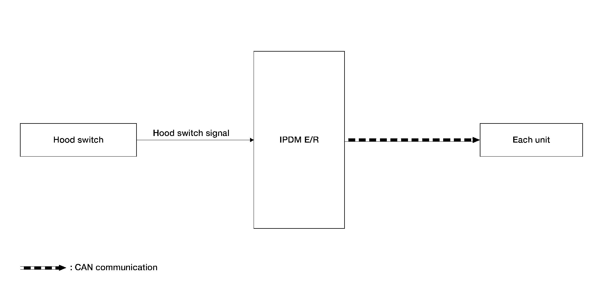
SYSTEM DIAGRAM
| Component | Function |
|---|---|
| Hood switch | Detects the hood condition (open or close), and transmits the hood switch signal to the IPDM E/R. |
| IPDM E/R | IPDM E/R has the signal transmission function that transmits each input signal to each unit. |
SIGNAL TRANSMISSION FUNCTION LIST
| Signal name | Input | Output | Description |
|---|---|---|---|
| Hood switch signal | Hood switch | BCM | Inputs the hood switch signal and transmits the hood switch signal via CAN communication. |
Power Consumption Control System
System Description
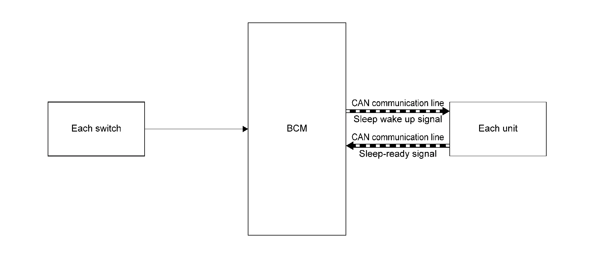
SYSTEM DIAGRAM
INPUT SIGNAL AND OUTPUT SIGNAL
Major signal transmission between each unit via CAN communication is shown in the following table:
| Component | Function |
|---|---|
| BCM |
|
| IPDM E/R |
|
| Combination meter | |
| Intelligent Key unit | |
| AV control unit | |
| TCU | |
| 8 CH CAN gateway | |
| ABS actuator and electric unit (control unit) | |
| Each switch | Each switch transmits the Nissan Ariya vehicle status to the BCM. |
DESCRIPTION
Outline
-
IPDM E/R incorporates a power consumption control function that reduces the power consumption according to the Nissan Ariya vehicle status.
-
IPDM E/R changes its status (control mode) with the sleep wake up signal received from BCM via CAN communication.
Normal mode (wake-up)
-
CAN communication is normally performed with other control units.
-
Individual unit control by IPDM E/R is normally performed.
Low power consumption mode (sleep)
-
Low power consumption control is active.
-
CAN transmission is stopped.
-
Sleep Mode Activation
-
IPDM E/R judges that the sleep-ready conditions are fulfilled when the ignition switch is OFF and none of the conditions below are present. Then it transmits a sleep-ready signal (ready) to BCM via CAN communication.
-
Outputting signals to actuators
-
Output requests are being received from control units via CAN communication.
-
-
IPDM E/R stops CAN communication and enters the low power consumption mode when it receives a sleep wake up signal (sleep) from BCM and the sleep-ready conditions are fulfilled.
Wake-Up Operation
-
IPDM E/R changes from the low power consumption mode to the normal mode when it receives a sleep wake up signal (wake up) from BCM or any of the following conditions is fulfilled. In addition, it transmits a sleep-ready signal (not-ready) to BCM via CAN communication to report the CAN communication start.
-
Ignition switch ON
-
Hood switch status changes.
-
An output request is received from a control unit via CAN communication.
-
Energy Management System
System Description
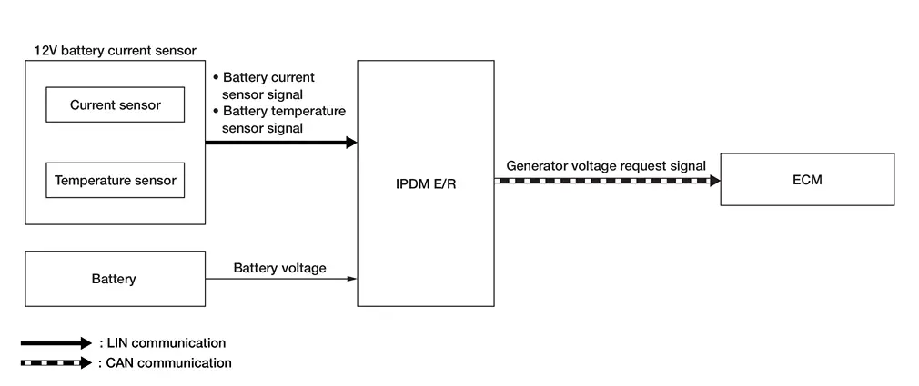
SYSTEM DIAGRAM
| Component | Function | |
|---|---|---|
| 12V battery current sensor | Current sensor | Detects the charging/discharging current of battery. |
| Temperature sensor | Detects the temperature around the battery. | |
| Battery | Battery supplies power supply voltage to each unit and part. | |
| IPDM E/R | IPDM E/R transmits the generator voltage request signal to the ECM via CAN communication according to the battery voltage, battery current sensor signal and battery temperature sensor signal. | |
| ECM | ECM controls the power generation voltage to the generator according to the request from the IPDM E/R received via CAN communication. | |
SIGNAL TRANSMISSION FUNCTION LIST
| Signal name | Input | Output | Description |
|---|---|---|---|
| Battery current sensor signal | 12V battery current sensor | IPDM E/R (LIN) | Transmits the battery current sensor signal via LIN communication. |
| Battery temperature sensor signal | 12V battery current sensor | IPDM E/R (LIN) | Transmits the battery temperature sensor signal via LIN communication. |
| Generator voltage request signal | IPDM E/R | ECM (CAN) | Transmits the generator voltage request signal via CAN communication. |
DESCRIPTION
IPDM E/R has an energy management system that recognizes the battery status from the following signals and maintains normal battery status. Refer to System Description.
-
Battery current sensor signal (received from 12V battery current sensor via LIN communication)
-
Battery temperature sensor signal (received from 12V battery current sensor via LIN communication)
-
Battery voltage (detected from battery)
Diagnosis System (ipdm E/r)
CONSULT Function (IPDM E/R)
APPLICATION ITEM
CONSULT performs the following functions via CAN communication with BCM.
| Diagnosis mode | Function Description |
|---|---|
| Self diagnosis result | Displays the diagnosis results judged by IPDM E/R. |
| Data monitor | Displays the real-time input/output data from IPDM E/R input/output data. |
| Work supports | The settings for IPDM E/R functions can be changed. |
| Active test | IPDM E/R can provide a drive signal to electronic components to check their operation. |
| ECU identification | Allows confirmation of IPDM E/R part number. |
| Replace ECU | Writes the Nissan Ariya vehicle specification when replacing the IPDM E/R |
ECU IDENTIFICATION
The IPDM E/R part number is displayed.
SELF DIAGNOSIS RESULT
Refer to DTC Index.
DATA MONITOR
NOTE:
The following table includes information (items) inapplicable to this Nissan Ariya vehicle. For information (items) applicable to this vehicle, refer to CONSULT display items.
| Monitor item | Description |
|---|---|
|
Parking lamp (LH) req (LIN) [Open/Close] |
Displays the status of the parking lamp LH request signal that the IPDM E/R transmits via LIN communication. |
|
DTRL (LH) req (LIN) [Open/Close] |
Displays the status of the daytime running light LH request signal that the IPDM E/R transmits via LIN communication. |
|
Headlamp LO (LH) req (LIN) [Open/Close] |
Displays the status of the headlamp LO LH request signal that the IPDM E/R transmits via LIN communication. |
|
Headlamp HI (LH) req (LIN) [Open/Close] |
Displays the status of the headlamp HI LH request signal that the IPDM E/R transmits via LIN communication. |
|
Parking lamp (RH) req (LIN) [Open/Close] |
Displays the status of the parking lamp RH request signal that the IPDM E/R transmits via LIN communication. |
|
DTRL (RH) req (LIN) [Open/Close] |
Displays the status of the daytime running light RH request signal that the IPDM E/R transmits via LIN communication. |
|
Headlamp HI (RH) req (LIN) [Open/Close] |
Displays the status of the headlamp HI RH request signal that the IPDM E/R transmits via LIN communication. |
|
Headlamp LO (RH) req (LIN) [Open/Close] |
Displays the status of the headlamp LO RH request signal that the IPDM E/R transmits via LIN communication. |
|
Battery status [OK/NG] |
Monitor the battery status from battery output. |
|
Headlamp warning RH (LIN) [Open/Close] |
Displays the status of low beam RH malfunction received from LED headlamp control module RH via LIN communication. |
|
Headlamp warning LH (LIN) [Open/Close] |
Displays the status of low beam LH malfunction received from LED headlamp control module RH via LIN communication. |
|
Front wiper relay [Off/On] |
Displays the front wiper relay drive status judged by the IPDM E/R. |
|
Horn relay [Off/On] |
Displays the horn relay drive status judged by the IPDM E/R. |
|
Front wiper HI/LO relay [Off/On] |
Displays the front wiper high relay drive status judged by the IPDM E/R. |
|
Compressor [Off/On] |
Displays the A/C compressor (magnetic clutch) output status judged by the IPDM E/R. |
|
Cooling fan relay-2 [Off/On] |
Displays the cooling fan relay drive status judged by the IPDM E/R. |
|
Ignition relay [Open/Close] |
Displays the status of the ignition relay judged by IPDM E/R. |
|
Hood switch [Open/Close] |
Displays the status of the hood switch judged by the IPDM E/R. |
|
Starter relay & starter control relay status [Off, Off/On, Off/invalid/On, On] |
Displays the status of the starter relay and starter cut relay that the IPDM E/R transmits via CAN communication. |
|
Reverse signal (CAN) [Off/On/NG] |
Displays the status of the reverse position signal that the IPDM E/R transmits via CAN communication. |
|
A/C relay [Off/On] |
Displays the status of the A/C compressor (magnetic clutch) output that the IPDM E/R transmits via CAN communication. |
|
Neutral switch (CAN) [Off/On/NG] |
Displays the status of the neutral position signal from the TCM via CAN communication. |
|
Hood switch (CAN) [NG/Open/Close] |
Displays the status of the hood switch signal that IPDM E/R transmits via CAN communication. |
|
Ignition power supply [Off/On] |
Displays the supply status of the ignition power supply that the IPDM E/R transmits via CAN communication. |
|
Front wiper stop position [Active/Stop position] |
Displays the status of the front wiper stop position signal that the IPDM E/R transmits via CAN communication. |
|
Stop/start status [Prohibit/Permit/No req] |
Displays the status of the idling stop system received from the ECM via CAN communication. |
|
Compressor (ECV) status [OK/NG] |
Displays the status of A/C compressor (ECV) malfunction diagnosis that the IPDM E/R transmits via CAN communication. |
|
Shift position [P/R/N/D/M/NG] |
Displays the status of the shift position signal received from the TCM via CAN communication. |
|
Front fog lamp request [Off/On] |
Displays the status of the front fog light request signal received from the BCM via CAN communication.
This item is only monitored on Nissan Ariya vehicles with front fog lamp. |
|
Ignition switch [Off/No request/On/START] |
Displays the status of the ignition switch ON signal received from the BCM via CAN communication. |
|
Position light request [Off/On] |
Displays the status of the position light request signal received from the BCM via CAN communication. |
|
Low beam request [Off/On] |
Displays the status of the low beam request signal received from the BCM via CAN communication. |
|
Horn request [NG/Return/Thft warn/Hrn chirp/Panic/Off/No request] |
Displays the status of the horn request signal received from the BCM via CAN communication. |
|
High beam request [Off/On] |
Displays the status of the high beam request signal received from the BCM via CAN communication. |
|
Front wiper request [Off/On] |
Displays the status of the front wiper request signal received from the BCM via CAN communication. |
|
Daytime running light request [Off/On] |
Displays the status of the daytime running light request signal received from the BCM via CAN communication. |
|
Cranking enable-ECM [Prohibit/Permit/Stop/No req] |
Displays the status of the cranking enable signal received from the ECM via CAN communication. |
|
Cranking enable-TCM [Unknown/Prohibit/Permit/Stop] |
Displays the status of the cranking enable signal received from the TCM via CAN communication. |
|
Easy fill tire alert horn req [Off/On] |
Displays the status of the horn request signal (easy fill tire alert horn request) received from the BCM via CAN communication. |
|
Compressor request [Off/On] |
Displays the status of the compressor request signal received via CAN communication. |
|
COOLING FAN REQ [%] |
Displays the status of the cooling fan request signal received via CAN communication. |
|
BATTERY VOLTAGE [V] |
Monitor the battery voltage from battery output. |
|
COMP ECV CURRENT [A] |
Display the status of electric current output to the A/C compressor (ECV) that the IPDM E/R transmits via CAN communication. |
|
Front fog lamp (LH) [%] |
Displays the front fog lamp LH output (PWM) status of the IPDM E/R.
This item is only monitored on Nissan Ariya vehicles with front fog lamp. |
|
Front fog lamp (RH) [%] |
Displays the front fog lamp RH output (PWM) status of the IPDM E/R.
This item is only monitored on Nissan Ariya vehicles with front fog lamp. |
|
Tail lamp (LH) [%] |
Displays the tail lamp LH output (PWM) status of the IPDM E/R. |
|
Tail lamp (RH) [%] |
Displays the tail lamp RH output (PWM) status of the IPDM E/R. |
|
Headlamp LO (RH) [%] |
Displays the headlamp LO RH output (PWM) status of the IPDM E/R. |
|
Headlamp LO (LH) [%] |
Displays the headlamp LO LH output (PWM) status of the IPDM E/R. |
|
Parking/DTRL (LH) output (LIN) [%] |
Displays the parking/daytime running light LH control signal output (PWM) status that the IPDM e/R transmits via LIN communication. |
|
Parking/DTRL (RH) output (LIN) [%] |
Displays the parking/daytime running light RH control signal output (PWM) status that the IPDM e/R transmits via LIN communication. |
|
T LAMP LH CIRC MALFUNCTN [―] |
Monitor the number of times that the Smart FET in the IPDM E/R reaches the retry upper limit of the tail lamp LH circuit.
When the number of tail lamp LH circuit retries count is 20, this item counts 1. |
|
NMB T LAMP LH CIRC RETRY [―] |
Monitor the number of times that the Smart FET in the IPDM E/R permits the retry of the tail lamp LH circuit.
When the number of short circuits in the tail lamp LH circuit count is 5 and ignition switch OFF to ON operation is detected, this item counts 1. |
|
Fr fog lamp (LH) circ malfunctn [―] |
Monitor the number of times that the Smart FET in the IPDM E/R reaches the retry upper limit of the front fog lamp LH circuit.
|
|
T LAMP RH CIRC MALFUNCTN [―] |
Monitor the number of times that the Smart FET in the IPDM E/R reaches the retry upper limit of the tail lamp RH circuit.
When the number of tail lamp RH circuit retries count is 20, this item counts 1. |
|
NMB T LAMP RH CIRC RETRY [―] |
Monitor the number of times that the Smart FET in the IPDM E/R permits the retry of the tail lamp RH circuit.
When the number of short circuits in the tail lamp RH circuit count is 5 and ignition switch OFF to ON operation is detected, this item counts 1. |
|
NMB T LAMP RH CIRC SHORT [―] |
Monitor the number of times that the Smart FET in the IPDM E/R detects the over current of the tail lamp RH circuit. |
|
NMB F FOG LH CIRC RETRY [―] |
Monitor the number of times that the Smart FET in the IPDM E/R permits the retry of the front fog lamp LH circuit.
|
|
NMB F FOG LH CIRC SHORT [―] |
Monitor the number of times that the Smart FET in the IPDM E/R detects the over current of the front fog lamp LH circuit.
This item is only monitored on Nissan Ariya vehicles with front fog lamp. |
|
F FOG RH CIRC MALFUNCTN [―] |
Monitor the number of times that the Smart FET in the IPDM E/R reaches the retry upper limit of the front fog lamp RH circuit.
|
|
NMB F FOG RH CIRC RETRY [―] |
Monitor the number of times that the Smart FET in the IPDM E/R permits the retry of the front fog lamp RH circuit.
|
|
NMB F FOG RH CIRC SHORT [―] |
Monitor the number of times that the Smart FET in the IPDM E/R detects the over current of the front fog lamp RH circuit.
This item is only monitored only Nissan Ariya vehicles with front fog lamp. |
|
NMB T LAMP LH CIRC SHORT [―] |
Monitor the number of times that the Smart FET in the IPDM E/R detects the over current of the tail lamp LH circuit. |
|
Nmb DTRL (LH) circ retry [―] |
Monitor the number of times that the Smart FET in the IPDM E/R permits the retry of the daytime running light LH circuit.
When the number of short circuits in the daytime running light LH circuit count is 5 and ignition switch OFF to ON operation is detected, this item counts 1. |
|
BAT DISCHARGE COUNT [―] |
Monitor the cumulative discharge value of the battery.
|
|
Cooling fan relay-3 [%] |
Displays the cooling fan relay-3 output (PWM) status of the IPDM E/R. |
|
Compressor (ECV) duty [%] |
Displays the A/C compressor (ECV) output (PWM) status of the IPDM E/R. |
|
Battery current sen value (LIN) [A] |
Displays the status of the battery current value received from the battery current sensor via LIN communication. |
ACTIVE TEST
| Test item | Operation | Description |
|---|---|---|
| HORN | OFF | Horn OFF. |
| ON | Operates the horn relay for 20ms. |
WORK SUPPORTS
| Work item | Description |
|---|---|
| Battery discharging current integrated value clear | In this mode, battery discharging current integrated value is cleared. |
REPLACE ECU
Refer to Description.
Other materials:
Removal and Installation. Battery Terminal with Fusible Link
Exploded View
Battery terminal with fusible link
: N·m (kg-m, in-lb)
: N·m (kg-m, ft-lb)
Removal and Installation
REMOVALDisconnect the battery cable from the negative terminal. Refer to Exploded View.
CAUTION:
To prevent damage to the parts, disc ...
Ecu Diagnosis Information. Ecm, Bcm, Intelligent Key Unit, Ipdm E/r
List of ECU Reference
ECU Reference
ECM
Values On The Diagnosis Tool
Values On The Diagnosis Tool
Physical Values
Physical Values
Fail-safe
Fail-safe
DTC Inspection Priority Chart
DTC Inspection Priority Chart
DTC Index
DTC Index
BCM
Reference Valu ...
Precaution. Precautions
Precaution for Supplemental Restraint System (SRS) "AIR BAG" and "SEAT BELT PRE-TENSIONER"
The Supplemental Restraint System such as “AIR BAG” and “SEAT BELT
PRE-TENSIONER”, used along with a front seat belt, helps to reduce the
risk or severity of injury to the driver and front passeng ...