Nissan Rogue (T33) 2021-Present Service Manual: Ipdm E/r :: Ecu Diagnosis Information. Ipdm E/r
Ipdm E/r
Values on the Diagnosis Tool
 NOTE:
NOTE:
The following table includes information (items) inapplicable to this Nissan Ariya vehicle. For information (items) applicable to this vehicle, refer to CONSULT display items.
| Monitor | Condition | Value/Status | |
|---|---|---|---|
| Parking lamp (LH) req (LIN) | Lighting switch OFF | Open | |
| Lighting switch 1ST | Close | ||
| DTRL (LH) req (LIN) | Lighting switch OFF | Open | |
| Lighting switch 1ST | Close | ||
| Headlamp LO (LH) req (LIN) | Lighting switch OFF | Open | |
| Lighting switch 2ND | Close | ||
| Headlamp HI (LH) req (LIN) | Lighting switch OFF or 1ST | Open | |
| Lighting switch 2ND | Lighting switch HI or PASSING | Close | |
| Parking lamp (RH) req (LIN) | Lighting switch OFF | Open | |
| Lighting switch 1ST | Close | ||
| DTRL (RH) req (LIN) | Lighting switch OFF | Open | |
| Lighting switch 1ST | Close | ||
| Headlamp HI (RH) req (LIN) | Lighting switch OFF of 1ST | Open | |
| Lighting switch 2ND | Lighting switch HI or PASSING | Close | |
| Headlamp LO (RH) req (LIN) | Lighting switch OFF | Open | |
| Lighting switch 2ND | Close | ||
|
BATTERY STATUS
This item is monitored only on Nissan Ariya vehicles with start/stop system. |
Engine: Idling | Battery status judgement result OK | OK |
| Battery status judgement result NG | NG | ||
| Headlamp warning (RH) (LIN) | Ignition switch OFF (auto ACC status) or ON | Headlamp LO (RH): Normal | Close |
| Headlamp LO (RH): Malfunction | Open | ||
| Headlamp warning (LH) (LIN) | Ignition switch OFF (auto ACC status) or ON | Headlamp LO (LH): Normal | Close |
| Headlamp LO (LH): Malfunction | Open | ||
| Front wiper relay | Ignition switch ON | Front wiper stop position | Off |
| Front wiper is operating | On | ||
| Horn relay | Horn ON | On | |
| Horn OFF | Off | ||
| Front wiper HI/LO relay | Ignition switch ON | Except front wiper HI operated | Off |
| Front wiper HI operated | On | ||
| Compressor | Engine running | A/C switch OFF | Off |
| A/C switch ON [A/C compressor (magnetic clutch) is operating] | On | ||
| Cooling fan relay-2 | Engine running | Cooling fan stop | Off |
|
On | ||
| Ignition relay | Ignition switch OFF | Open | |
| Ignition switch ON | Close | ||
| Hood switch | Close the hood | Open | |
| Open the hood | Close | ||
| Starter relay & starter control relay status | Starter relay and starter cut relay are OFF | Off, Off | |
| Starter relay is ON | On, Off | ||
| Starter relay and starter cut relay are ON | On, On | ||
| Transmits invalid CAN signal | invalid | ||
| Reverse signal (CAN) | Ignition switch ON | R range | On |
| Except R range | Off | ||
| Transmits invalid CAN signal | NG | ||
| A/C relay | Engine running | A/C switch OFF | Off |
| A/C switch ON [A/C compressor (magnetic clutch) is operating] | On | ||
| Neutral switch (CAN) | Ignition switch ON | Shift selector in any position other than neutral | Off |
| Shift selector in neutral position | On | ||
| Transmits invalid CAN signal | NG | ||
| Hood switch (CAN) | Open the hood | Open | |
| Close the hood | Close | ||
| Transmits invalid CAN signal | NG | ||
| Ignition power supply | Ignition switch ON | On | |
| Ignition switch OFF | Off | ||
| Front wiper stop position | Ignition switch ON | Except front wiper stop position | Active |
| Front wiper stop position | Stop position | ||
| Stop/start status | Start/stop system error | No req | |
| Start/stop system operation condition | Not satisfied | Prohibit | |
| Satisfied | Permit | ||
| Compressor (ECV) status | ECV control output | Normal | OK |
| Malfunction | NG | ||
| Shift position | Engine running | Manual mode | M |
| D range | D | ||
| N range | N | ||
| R range | R | ||
| P range | P | ||
| Receives invalid CAN signal | NG | ||
|
Front fog lamp request
This item is only monitored on Nissan Ariya vehicles with front fog lamp. |
Lighting switch 1ST | Front fog lamp switch OFF | Off |
| Front fog lamp switch ON | On | ||
| Ignition switch | Ignition switch OFF | Off | |
| Ignition switch ON | On | ||
| Ignition switch START | START | ||
| — | No request | ||
| Position light request | Lighting switch OFF | Off | |
| Lighting switch 1ST | On | ||
| Low beam request | Lighting switch OFF | Off | |
| Lighting switch 2ND | On | ||
| Horn request | C mode (horn chirp mode) return horn request | Return | |
| Theft warning alarm request | Thft warn | ||
| Horn chirp request | Hrn chirp | ||
| Panic alarm request | Panic | ||
| Horn OFF request | Off | ||
| No request | No request | ||
| Receives invalid CAN signal | NG | ||
| High beam request | Lighting switch 2ND | Lighting switch LO | Off |
| Lighting switch HI | On | ||
| Front wiper request | Ignition switch ON | Front wiper switch ON | On |
| Front wiper switch OFF | Off | ||
|
Daytime running light request
This item is only monitored on Nissan Ariya vehicles with daytime running light. |
Engine running | Lighting switch 1ST | Off |
| Lighting switch OFF | On | ||
| Cranking enable-ECM | Engine crank condition | Not satisfied | Prohibit |
| Satisfied | Permit | ||
| — | Stop | ||
| Receives invalid CAN signal | No req | ||
| Cranking enable-TCM | Engine crank condition | Not satisfied | Prohibit |
| Satisfied | Permit | ||
| — | Stop | ||
| Receives invalid CAN signal | No req | ||
| Easy fill tire alert horn req | Easy fill tire alert ON | On | |
| Easy fill tire alert OFF | Off | ||
| Compressor | Engine running | A/C switch ON [A/C compressor (magnetic clutch) is operating] | On |
| A/C switch OFF | Off | ||
| COOLING FAN REQ | Engine running | 0 – 100% | |
| BATTERY VOLTAGE | Ignition switch ON | 11 V – 14 V | |
| COMP ECV CURRENT | Engine running | A/C switch ON [A/C compressor (ECV) is operating] | 0.00 A – 1.00 A |
| A/C switch OFF | 0.00 A | ||
|
Front fog lamp (LH)
This item is monitored only on Nissan Ariya vehicles with front fog lamp. |
Lighting switch 1ST | Front fog lamp switch OFF | 0% |
| Front fog lamp switch ON | 100% | ||
|
Front fog lamp (RH)
This item is monitored only on Nissan Ariya vehicles with front fog lamp. |
Lighting switch 1ST | Front fog lamp switch OFF | 0% |
| Front fog lamp switch ON | 100% | ||
| Tail lamp (LH) | Lighting switch OFF | 0.0% | |
| Lighting switch 1ST | 100.0% | ||
| Tail lamp (RH) | Lighting switch OFF | 0% | |
| Lighting switch 1ST | 100% | ||
| Headlamp LO (RH) | Lighting switch light OFF | 0% | |
| Lighting switch 2ND | 100% | ||
| Headlamp LO (LH) | Lighting switch light OFF | 0% | |
| Lighting switch 2ND | 100% | ||
| Parking/DTRL (LH) output (LIN) | Engine running and parking brake is released |
|
100.0% |
| Lighting switch 2ND | 6.0% | ||
| Engine stop |
|
0.0% | |
| Parking/DTRL (RH) output (LIN) | Engine running and parking brake is released |
|
100.0% |
| Lighting switch 2ND | 6.0% | ||
| Engine stop |
|
0.0% | |
| T LAMP LH CIRC MALFUNCTN | Tail lamp LH circuit reaches the retry upper limit. | 0 – 1 | |
| NMB T LAMP LH CIRC RETRY | Retry of tail lamp LH circuit is permitted. | 0 – 20 | |
| Fr fog lamp (LH) circ malfunctn | Front fog lamp LH power supply circuit reaches the retry upper limit. | 0 – 1 | |
| T LAMP RH CIRC MALFUNCTN | Tail lamp RH circuit reaches the retry upper limit. | 0 – 1 | |
| NMB T LAMP RH CIRC RETRY | Retry of tail lamp RH circuit is permitted. | 0 – 20 | |
| NMB T LAMP RH CIRC SHORT | Tail lamp RH circuit detects over current. | 0 – 5 | |
|
NMB F FOG LH CIRC RETRY
This item is only monitored on Nissan Ariya vehicles with front fog lamp. |
Retry of front fog lamp LH circuit is permitted. | 0 – 20 | |
|
NMB F FOG LH CIRC SHORT
This item is only monitored on Nissan Ariya vehicles with front fog lamp. |
Front fog lamp LH circuit detects over current. | 0 – 5 | |
|
F FOG RH CIRC MALFUNCTN
This item is only monitored on Nissan Ariya vehicles with front fog lamp. |
Front fog lamp RH circuit reaches the retry upper limit. | 0 – 1 | |
|
NMB F FOG RH CIRC RETRY
This item is only monitored on Nissan Ariya vehicles with front fog lamp. |
Retry of front fog lamp RH circuit is permitted. | 0 – 20 | |
|
NMB F FOG RH CIRC SHORT
This item is only monitored on Nissan Ariya vehicles with front fog lamp. |
Front fog lamp RH circuit detects over current. | 0 – 5 | |
| NMB T LAMP LH CIRC SHORT | Tail lamp LH circuit detects over current. | 0 – 5 | |
| NMB DTRL (LH) circ retry | Retry of daytime running light LH circuit is permitted. | 0 – 20 | |
|
BAT DISCHARGE COUNT
This item is monitored only on Nissan Ariya vehicles with start/stop system. |
Ignition switch ON | Less than 65000 | |
| Cooling fan relay-3 | Engine running | Cooling fan stop | 0% |
|
0 – 100% | ||
| Compressor ECV duty | Engine running | A/C switch OFF | 0% |
| A/C switch ON [A/C compressor (ECV) is operating] | 0 – 100% | ||
| Battery current sensor value (LIN) |
|
(–200.00) – (+300.00) A | |
Reference Value
TERMINAL LAYOUT
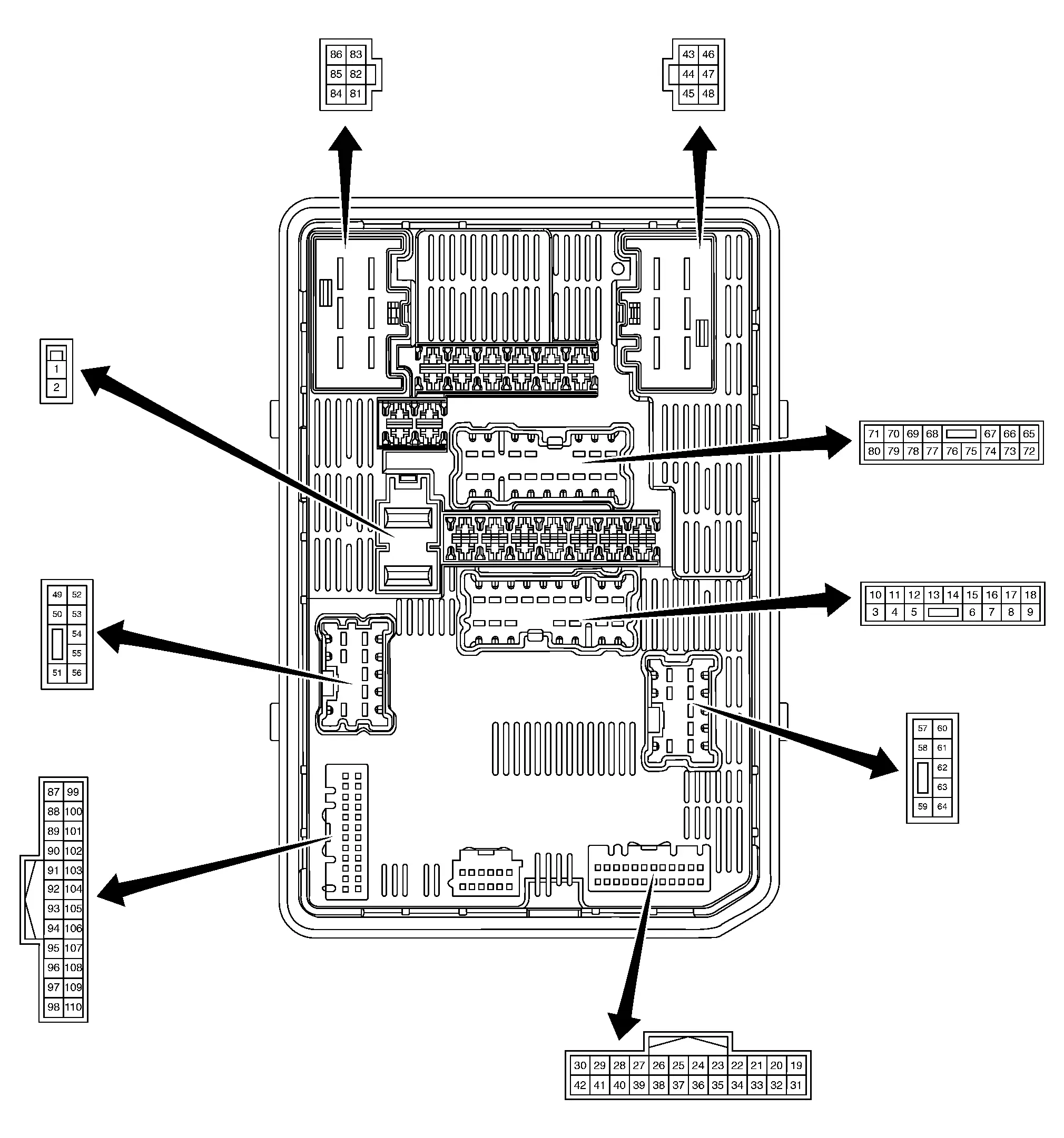
PHYSICAL VALUES
|
Terminal No. (Wire color) | Description | Condition |
Value (Approx.) | |||
|---|---|---|---|---|---|---|
| Signal name | Input/Output | |||||
| + | - | |||||
|
1 (W) |
Ground | Battery power supply | Input | Ignition switch OFF | Battery voltage | |
|
2 (L) |
Ground | Battery power supply | Input | Ignition switch OFF | Battery voltage | |
|
4 (R) |
Ground | Tail lamp power supply | Output |
|
0 V | |
| Lighting switch 1ST | Battery voltage | |||||
|
5 (Y) |
Ground | Front washer pump relay control | Output | Ignition switch ON | Front washer switch OFF | Battery voltage |
| Front washer switch ON | 0 V | |||||
|
6 (SB) |
Ground | Rear washer pump relay control | Output | Ignition switch ON | Rear washer switch OFF | Battery voltage |
| Rear washer switch ON | 0 V | |||||
|
8 (LG) |
Ground | ECM relay output | Output | Ignition switch OFF | 0 V | |
| Ignition switch ON | Battery voltage | |||||
|
9 (L) |
Ground | Horn relay control | Output | Horn OFF | Battery voltage | |
| Horn ON | 0 V | |||||
|
11 (BR) |
Ground | Ignition relay-1 output | Output | Ignition switch OFF | 0 V | |
| Ignition switch ON | Battery voltage | |||||
|
12 (B) |
Ground | Ground | — | Ignition switch OFF | 0 V | |
|
19 (LG) |
Ground | Ignition relay-1 output | Output | Ignition switch OFF | 0 V | |
| Ignition switch ON | Battery voltage | |||||
|
22 (P) |
Ground | CAN-Low | Input/Output | — | — | |
|
24 (L) |
Ground | CAN-High | Input/Output | — | — | |
|
31 (B) |
Ground | Ground | — | Ignition switch OFF | 0 V | |
|
33 (BR) |
Ground | Front wiper stop position signal | Input | Ignition switch ON | Front wiper stop position | 0 V |
| Other than above | Battery voltage | |||||
|
37 (G) |
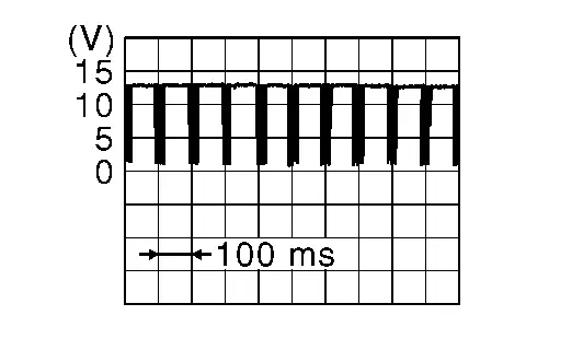
Ground | LIN communication (12V battery current sensor) | Input/Output | Ignition switch ON |
|
|
|
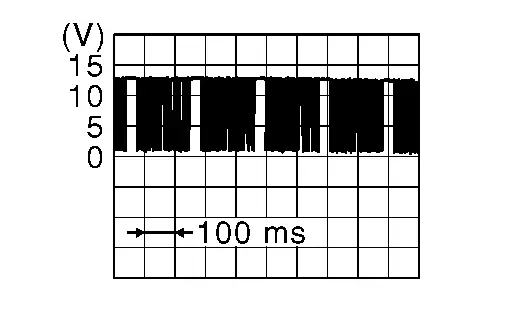
38 (R) |
Ground | LIN communication (headlamp) | Input/Output | Ignition switch ON |
|
|
|
43 (LG) |
Ground | Ignition relay-1 output | Output | Ignition switch OFF | 0 V | |
| Ignition switch ON | Battery voltage | |||||
|
45 (V) |
Ground | Front wiper motor HI power supply | Output | Ignition switch ON | Front wiper switch OFF | 0 V |
| Front wiper switch HI | Battery voltage | |||||
|
46 (W) |
Ground | Fuel pump power supply | Output | Ignition switch OFF | 0 V | |
| Ignition switch ON | Battery voltage | |||||
|
47 (B) |
Ground | Ground | — | Ignition switch OFF | 0 V | |
|
48 (Y) |
Ground | Front wiper motor LO power supply | Output | Ignition switch ON | Front wiper switch OFF | 0 V |
| Front wiper switch LO | Battery voltage | |||||
|
50 (L) |
Ground | Headlamp LH control | Output | Ignition switch OFF | 0 V | |
| Ignition switch ON | Battery voltage | |||||
|
52 (SB) |
Ground | Hood switch signal | Input | Hood closed | 0 V | |
| Hood open | Battery voltage | |||||
|
55 (G) |
Ground | Ignition relay-1 output | Output | Ignition switch OFF | 0 V | |
| Ignition switch ON | Battery voltage | |||||
|
62 (P) |
Ground | Headlamp RH control | Output | Ignition switch OFF | 0 V | |
| Ignition switch ON | Battery voltage | |||||
|
65 (P) |
Ground | A/C compressor (magnetic clutch) power supply | Output | Engine running | A/C switch OFF | 0 V |
|
A/C switch ON [A/C compressor (magnetic clutch) is operating] |
Battery voltage | |||||
|
66 (R) |
Ground | ECM relay output | Output | Ignition switch OFF | 0 V | |
| Ignition switch ON | Battery voltage | |||||
|
70 (P) |
Ground | Ignition relay-1 output | Output | Ignition switch OFF | 0 V | |
| Ignition switch ON | Battery voltage | |||||
|
71 (SB) |
Ground | Ignition relay-1 output | Output | Ignition switch OFF | 0 V | |
| Ignition switch ON | Battery voltage | |||||
|
73 (G) |
Ground | ECM relay output | Output | Ignition switch OFF | 0 V | |
| Ignition switch ON | Battery voltage | |||||
|
75 (V) |
Ground | ECM relay output | Output | Ignition switch OFF | 0 V | |
| Ignition switch ON | Battery voltage | |||||
|
76 (P) |
Ground | Fuel pump relay control | Input | Ignition switch OFF | Battery voltage | |
| Ignition switch ON | 0 V | |||||
|
78 (BR) |
Ground | ECM relay output | Output | Ignition switch OFF | 0 V | |
| Ignition switch ON | Battery voltage | |||||
|
81 (L) |
Ground | Battery power supply | Input | Ignition switch OFF | Battery voltage | |
|
83 (G) |
Ground | Starter motor power supply | Output | Other than at engine cranking | 0 V | |
| At engine cranking | Battery voltage | |||||
|
86 (GR) |
Ground | Starter relay power supply | Input | Other than at engine cranking |
4 V (IPDM E/R always outputs the voltage to detect the ON/OFF state of starter cut relay) |
|
| At engine cranking | Battery voltage | |||||
|
93 (LG) |
Ground | ECM relay control | Input | Ignition switch OFF | Battery voltage | |
| Ignition switch ON | 0 V | |||||
|
98 (Y) |
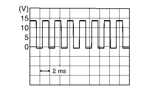
Ground | A/C compressor (ECV) control | Output | A/C compressor (ECV) duty ratio: 0% | 0 V | |
| A/C compressor (ECV) duty ratio: 40% |
|
|||||
| A/C compressor (ECV) duty ratio: 80 – 90% | Battery voltage | |||||
|
106 (W) |
Ground | Cooling fan control | Output | — | — | |
Fail-safe
FAIL-SAFE CONTROL BY DTC
IPDM E/R performs fail-safe control when any DTC are detected.
| DTC No. | CONSULT display | Fail-safe | |
|---|---|---|---|
| B12A4-81 | Battery current sensor | [INVALID SERIAL DATA RECEIVED] | Fix the power generation command value to 14.3 V. |
| B12A4-92 | Battery current sensor | [PFM/INCORRECT OPERATN] | |
| B20A2-87 | Headlamp (RH) LIN communication | [MISSING MESSAGE] |
|
| B20A4-87 | Headlamp (LH) LIN communication | [MISSING MESSAGE] | |
| B20C7-11 | A/C clutch | [CIRCUIT SHORT TO GROUND] | Inhibit A/C compressor (magnetic clutch) operation. |
| B20C7-15 | A/C clutch | [CIRC SHORT TO BATT OR OPEN] | |
| B20C8-14 | ECV (ELECTRICAL CONTROL VALVE) | [CIRC SHORT TO GRND OR OPEN] | Inhibit A/C compressor (ECV) operation. |
| B20D4-11 | TAIL LAMP LH PWR SPLY CIRC | [CIRCUIT SHORT TO GROUND] |
Shuts off the power supply to the following power supply circuits until the license plate lamp, side marker lamp and tail lamp ON conditions are no longer satisfied:
|
| B20E2-96 | LED HEADLAMP RH | [CMPNENT INTERNAL MLFNCTN] |
|
| B20E3-96 | LED HEADLAMP LH | [CMPNENT INTERNAL MLFNCTN] | |
| U0073-00 | Control module comm Bus A Off | [NO SUBTYPE INFO] | Refer to CAN COMMUNICATION CONTROL. |
| U2140-87 | CAN comm err (ECM) | [MISSING MESSAGE] | |
| U214F-87 | CAN comm err (BCM) | [MISSING MESSAGE] | |
CAN COMMUNICATION CONTROL
When CAN communication with ECM and BCM is impossible, IPDM E/R performs fail-safe control. After CAN communication recovers normally, it also returns to normal control.
If No CAN Communication Is Available With ECM
| Control part | Fail-safe operation |
|---|---|
| Cooling fan |
|
| A/C compressor (magnetic clutch) | A/C compressor (magnetic clutch) OFF |
If No CAN Communication Is Available With BCM
| Control part | Fail-safe operation |
|---|---|
| Headlamp |
|
|
|
| Front wiper |
|
| Daytime running light | Daytime running light: OFF |
| Ignition relay | The status just before activation of fail-safe is maintained. |
| Starter motor | Starter relay: OFF |
IGNITION RELAY CONTROL
-
IPDM E/R monitors the voltage at the contact circuit of the ignition relay inside it.
-
IPDM E/R judges the ignition relay error if the voltage differs between the contact circuit.
| Voltage judgement | IPDM E/R judgement | Operation | |
|---|---|---|---|
| Ignition relay contact side | Ignition relay control condition | ||
| ON | ON | Ignition relay ON normal | — |
| OFF | OFF | Ignition relay OFF normal | — |
| ON | OFF | Ignition relay ON stuck | Detects DTC [B20DD-73: IGN RELAY ON CIRC] |
| OFF | ON | Ignition relay OFF stuck | Detects DTC [B20DE-72: IGN RELAY OFF CIRC] |
FRONT WIPER CONTROL
IPDM E/R detects front wiper stop position by front wiper stop position signal.
When front wiper stop position signal is in the condition listed below while the front wiper is operating, IPDM E/R activates the fail-safe.
| Ignition switch | Front wiper switch | Front wiper stop position signal | Fail-safe |
|---|---|---|---|
| ON | OFF | The signal does not change from the battery voltage for 10 seconds. | Stops front wiper power supply for 20 seconds |
| Except OFF | The signal does not change for 10 seconds. |
DTC Inspection Priority Chart
| Priority | DTC No. | CONSULT display | |
|---|---|---|---|
| 1 | U0073-00 | Control module comm Bus A Off | [NO SUBTYPE INFO] |
| U2140-87 | CAN comm err (ECM) | [MISSING MESSAGE] | |
| U2141-87 | CAN comm err (TCM) | [MISSING MESSAGE] | |
| U2148-87 | CAN comm err (brake control unit) | [MISSING MESSAGE] | |
| U214E-87 | CAN comm err (combination meter) | [MISSING MESSAGE] | |
| U214F-87 | CAN comm err (BCM) | [MISSING MESSAGE] | |
| U2153-87 | CAN comm err (HVAC) | [MISSING MESSAGE] | |
| U2159-87 | CAN comm err (steering control unit) | [MISSING MESSAGE] | |
| U2176-87 | CAN comm err (CCM/ST angle sensor) | [MISSING MESSAGE] | |
| 2 | B120E-42 | IPDM E/R | [MEMORY ERROR] |
| B120E-55 | IPDM E/R | [NOT CONFIGURED] | |
| 3 | B12A3-72 | Fuel pump Off circuit | [ACTUATOR STUCK OPEN] |
| B12A4-81 | Battery current sensor | [INVALID SERIAL DATA RECEIVED] | |
| B12A4-92 | Battery current sensor | [PFM/INCORRECT OPERATN] | |
| B12A4-94 | Battery current sensor | [UNEXPECTED OPERATION] | |
| B20A1-16 | IPDM E/R | [CIRC VOLT BELOW THRESHOLD] | |
| B20A1-72 | IPDM E/R | [ACTUATOR STUCK OPEN] | |
| B20DD-73 | IGN RELAY ON CIRC | [ACTUATOR STUCK CLOSED] | |
| B20DE-72 | IGN RELAY OFF CIRC | [ACTUATOR STUCK OPEN] | |
| 4 | B20A2-87 | Headlamp (RH) LIN communication | [MISSING MESSAGE] |
| B20A4-87 | Headlamp (LH) LIN communication | [MISSING MESSAGE] | |
| B20C7-11 | A/C clutch | [CIRCUIT SHORT TO GROUND] | |
| B20C7-15 | A/C clutch | [CIRC SHORT TO BATT OR OPEN] | |
| B20C8-14 | ECV (ELECTRICAL CONTROL VALVE) | [CIRC SHORT TO GRND OR OPEN] | |
| B20D4-11 | TAIL LAMP LH PWR SPLY CIRC | [CIRCUIT SHORT TO GROUND] | |
| B20E2-96 | LED HEADLAMP RH | [CMPNENT INTERNAL MLFNCTN] | |
| B20E3-96 | LED HEADLAMP LH | [CMPNENT INTERNAL MLFNCTN] | |
DTC Index
NOTE:
The details of time display are as follows:
-
CRNT: A malfunction is detected now.
-
PASS: A malfunction was detected in the past.
Ă—: Applicable
| DTC No. | CONSULT display | Fail-safe | Reference | |
|---|---|---|---|---|
| B120E-42 | IPDM E/R | [MEMORY ERROR] | ― | DTC Description |
| B120E-55 | IPDM E/R | [NOT CONFIGURED] | ― | DTC Description |
| B12A3-72 | Fuel pump Off circuit | [ACTUATOR STUCK OPEN] | ― | DTC Description |
| B12A4-81 | Battery current sensor | [INVALID SERIAL DATA RECEIVED] | Ă— | DTC Description |
| B12A4-92 | Battery current sensor | [PFM/INCORRECT OPERATN] | Ă— | DTC Description |
| B12A4-94 | Battery current sensor | [UNEXPECTED OPERATION] | ― | DTC Description |
| B20A1-16 | IPDM E/R | [CIRC VOLT BELOW THRESHOLD] | ― | DTC Description |
| B20A1-72 | IPDM E/R | [ACTUATOR STUCK OPEN] | ― | DTC Description |
| B20A2-87 | Headlamp (RH) LIN communication | [MISSING MESSAGE] | Ă— | DTC Description |
| B20A4-87 | Headlamp (LH) LIN communication | [MISSING MESSAGE] | Ă— | DTC Description |
| B20C7-11 | A/C clutch | [CIRCUIT SHORT TO GROUND] | Ă— | DTC Description (with automatic air conditioning) or DTC Description (with manual air conditioning) |
| B20C7-15 | A/C clutch | [CIRC SHORT TO BATT OR OPEN] | Ă— | DTC Description (with automatic air conditioning) or DTC Description (with manual air conditioning) |
| B20C8-14 | ECV (ELECTRICAL CONTROL VALVE) | [CIRC SHORT TO GRND OR OPEN] | Ă— | DTC Description (with automatic air conditioning) or DTC Description (with manual air conditioning) |
| B20D4-11 | TAIL LAMP LH PWR SPLY CIRC | [CIRCUIT SHORT TO GROUND] | Ă— | DTC Description |
| B20DD-73 | IGN RELAY ON CIRC | [ACTUATOR STUCK CLOSED] | Ă— | DTC Description |
| B20DE-72 | IGN RELAY OFF CIRC | [ACTUATOR STUCK OPEN] | Ă— | DTC Description |
| B20E2-96 | LED HEADLAMP RH | [CMPNENT INTERNAL MLFNCTN] | Ă— | DTC Description |
| B20E3-96 | LED HEADLAMP LH | [CMPNENT INTERNAL MLFNCTN] | Ă— | DTC Description |
| U0073-00 | Control module comm Bus A Off | [NO SUBTYPE INFO] | Ă— | DTC Description |
Ă—: Applicable
| DTC No. | CONSULT display | Fail-safe | Reference | |
|---|---|---|---|---|
| U2140-87 | CAN comm err (ECM) | [MISSING MESSAGE] | Ă— | DTC Description |
| U2141-87 | CAN comm err (TCM) | [MISSING MESSAGE] | ― | DTC Description |
| U2148-87 | CAN comm err (brake control unit) | [MISSING MESSAGE] | ― | DTC Description |
| U214E-87 | CAN comm err (combination meter) | [MISSING MESSAGE] | ― | DTC Description |
| U214F-87 | CAN comm err (BCM) | [MISSING MESSAGE] | Ă— | DTC Description |
| U2153-87 | CAN comm err (HVAC) | [MISSING MESSAGE] | ― | DTC Description |
| U2159-87 | CAN comm err (steering control unit) | [MISSING MESSAGE] | ― | DTC Description |
| U2176-87 | CAN comm err (CCM/ST angle sensor) | [MISSING MESSAGE] | — | DTC Description |
Other materials:
U1321-55 Configuration Unfinished
DTC Description
DTC DETECTION LOGIC DTC No.
CONSULT screen terms
(Trouble diagnosis content) DTC detection condition
U1321–55
Config unfinished
(Configuration unfinished)
Diagnosis condition
When ignition switch is ON
Signal (terminal)
—
Threshold
Configuration ...
System Description. System. Power Window System
Power Window System
System Description
SYSTEM DIAGRAM Component Function
Front door switch
Detects front door open/close condition and transmits door switch signal to BCM.
BCM
Controls power window relay.
Controls retained power function.
Power window main switch ...
C10b4-98 Overheat
DTC Description
DTC DETECTION LOGIC DTC No.
CONSULT screen terms
(Trouble diagnosis content) DTC detection condition
C10B4
98
Overheat
(Overheat)
Diagnosis condition
When ignition switch is ON
Signal (terminal)
—
Threshold
System is high temperature status.
...