Nissan Rogue (T33) 2021-Present Service Manual: Information Display (combination Meter)
Door Open Warning
DESIGN/PURPOSE
Information display warns the driver that each door is open or is not fully closed.
| Symbol | Message |
|---|---|
|
|
– |
SYNCHRONIZATION WITH MASTER WARNING LAMP
Synchronization is applied.
Refer to Master Warning Lamp.
SYSTEM DIAGRAM
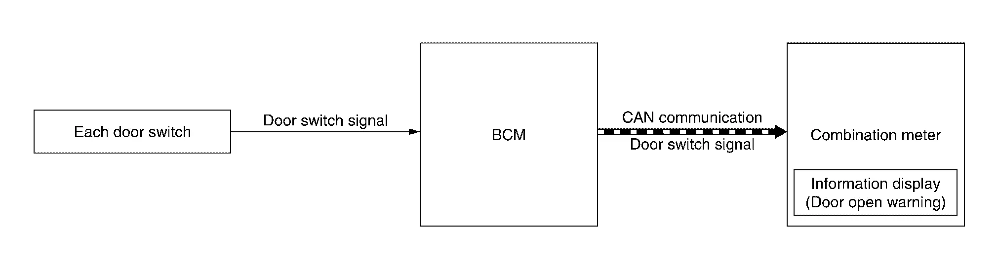
SIGNAL PATH
-
BCM transmits door switch signal to combination meter via CAN communication.
-
When combination meter judges according to received door switch signal that a door is open or not fully closed, door open warning displays.
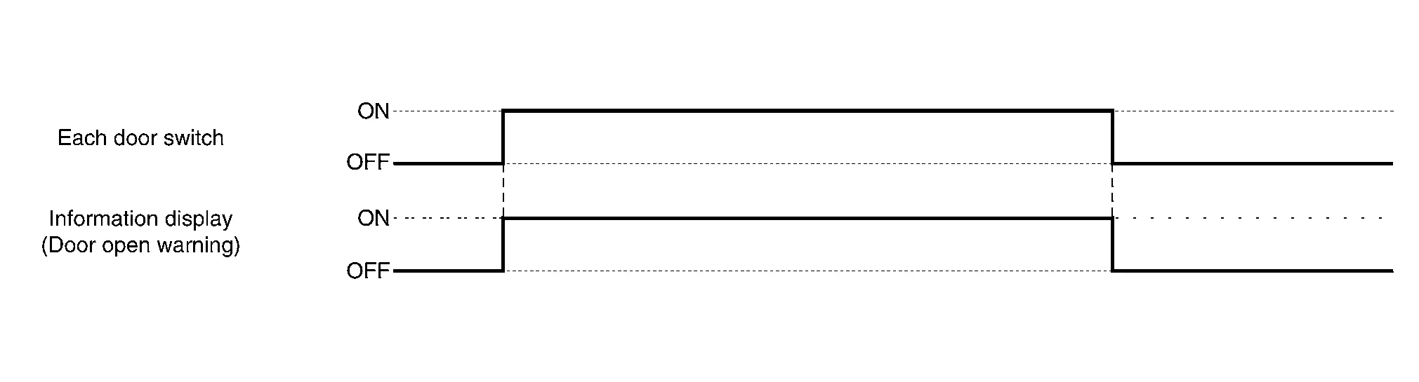
WARNING/INDICATOR OPERATIONG CONDITION
Each door switch is ON
WARNING/INDICATOR CANCEL CONDITION
All door switches are OFF
TIMING CHART
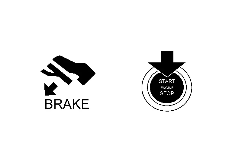
Engine Start Information
DESIGN/PURPOSE
Information display informs the driver that the engine can be started.
| Symbol | Message | |
|---|---|---|
|
|
Push brake and start switch to drive | |
SYNCHRONIZATION WITH MASTER WARNING LAMP
No applicable
SYSTEM DIAGRAM
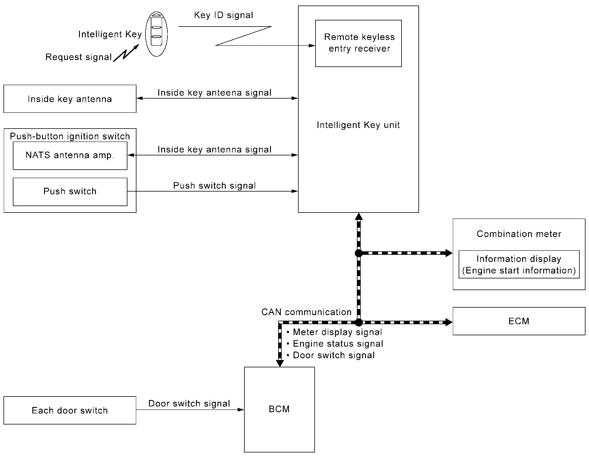
SIGNAL PATH
-
Intelligent Key unit receives engine status signal from ECM via CAN communication and checks that the engine can be started.
-
When Intelligent Key unit detects that the engine can be started, meter display signal is transmitted by Intelligent Key unit to combination meter via CAN communication.
-
When combination meter receives meter display signal, engine start information displays.
WARNING/INDICATOR OPERATION CONDITION
When Ignition Switch is ON.
When all of the following conditions are satisfied.
-
Ignition switch is in ON position.
-
Shift position: P position.
-
Engine can be started.
When Ignition Switch is Other Than ON.
When all of the following conditions are satisfied.
-
One condition of A
-
All conditions of B
A condition B condition -
Any door is open → All door is closed
-
Push-button ignition switch: Pressed
-
Intelligent Key backside is contacted to push-button ignition switch while brake pedal is depressed.
-
Ignition switch: OFF position
-
Shift position: P position
-
Registered Intelligent Key is detected inside Nissan Ariya vehicle.
-
WARNING/INDICATOR CANCEL CONDITION
When Ignition Switch is ON.
When any of the following conditions are satisfied.
-
Engine is started.
-
Shift position: Other than P position.
When Ignition Switch is Other than ON.
When any of the following conditions are satisfied.
-
Shift position: Other than P position.
-
Registered Intelligent Key is not detected inside the Nissan Ariya vehicle.
-
When Intelligent Key unit receives Intelligent Key button operation via remote keyless entry receiver.
-
When Intelligent Key unit receives door request switch signal from door request switch.
-
After 15 seconds are passed since the engine start information is displayed.
Intelligent Key Low Battery Warning
DESIGN/PURPOSE
Information display warns the driver that Intelligent Key battery level is low.
 NOTE:
NOTE:
Information display does not display when Intelligent Key battery is discharged.
| Symbol | Message |
|---|---|
|
|
Key Battery Low |
SYNCHRONIZATION WITH MASTER WARNING LAMP
No applicable
SYSTEM DIAGRAM
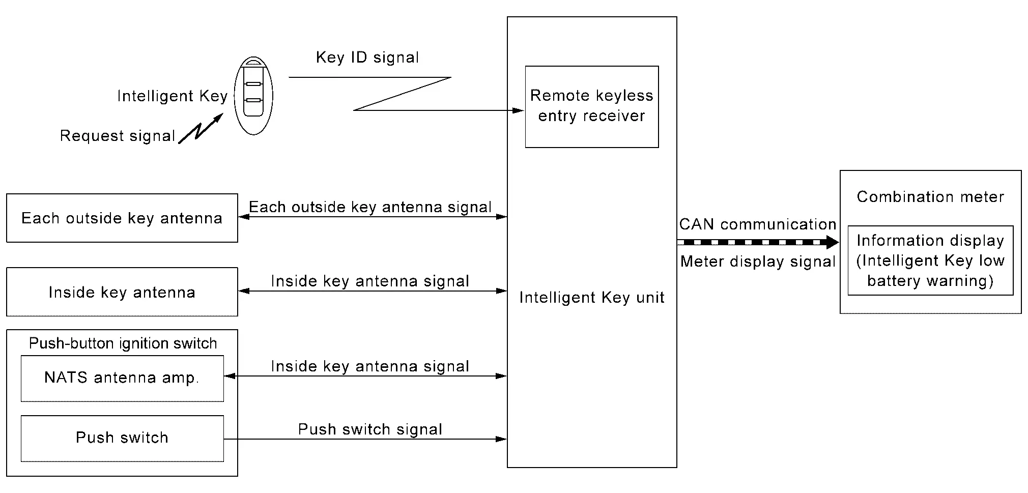
SIGNAL PATH
-
When Intelligent Key receives request signal from inside key antenna or outside key antenna, transmits key ID signal is transmitted from Intelligent Key to Intelligent Key unit.
-
Intelligent Key unit receives key ID signal via remote keyless entry receiver and detects that Intelligent Key battery level is low.
-
When Intelligent Key unit detects that ignition switch is ON, meter display signal is transmitted by Intelligent Key unit to combination meter via CAN communication.
-
When combination meter receives meter display signal, Intelligent Key low battery warning displays.
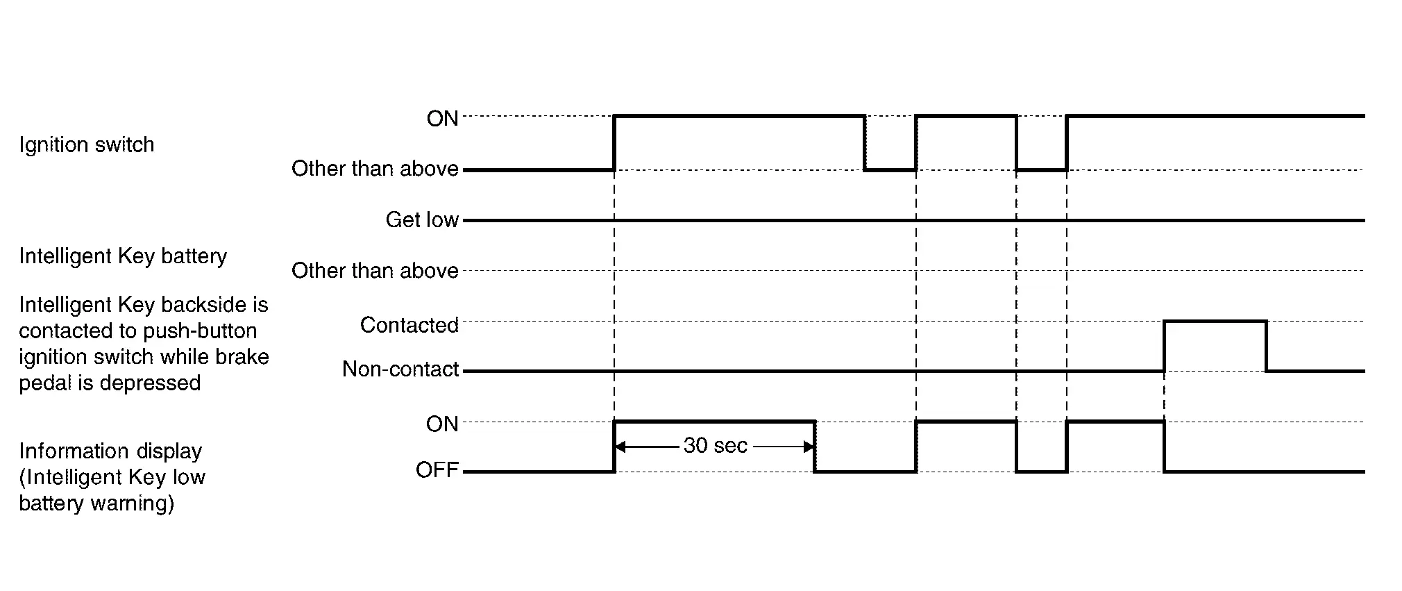
WARNING/INDICATOR OPERATING CONDITION
When all of the following conditions are satisfied.
-
Ignition switch is in ON position.
-
Intelligent Key battery level is low.
WARNING/INDICATOR CANCEL CONDITION
When any of the following conditions are satisfied.
-
After 30 seconds are passed since the Intelligent Key low battery warning is displayed
-
Ignition switch is in a position other than ON.
-
When Intelligent Key backside is contacted to push-button ignition switch while brake pedal is depressed.
TIMING CHART
Intelligent Key System Malfunction
DESIGN/PURPOSE
Information display warns the driver that Intelligent Key system malfunctions or that engine cannot be started.
| Symbol | Message |
|---|---|
|
|
Key System Error See Owner’s Manual |

SYNCHRONIZATION WITH MASTER WARNING LAMP
Synchronization is applied.
Refer to Master Warning Lamp.
SYSTEM DIAGRAM
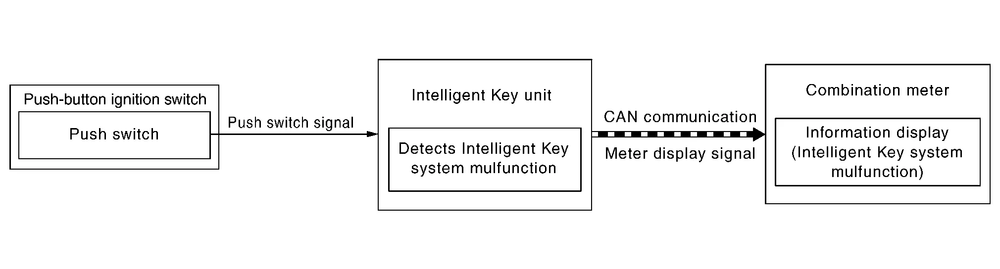
SIGNAL PATH
-
When Intelligent Key unit detects that Intelligent Key system malfunctions or that the engine cannot be started, meter display signal is transmitted by Intelligent Key unit to combination meter via CAN communication.
-
When combination meter receives meter display signal, Intelligent Key system malfunction displays.
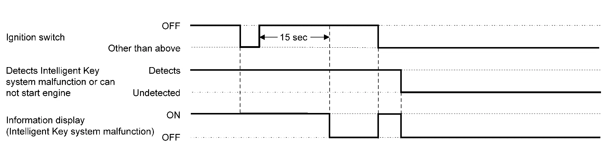
WARNING/INDICATOR OPERATING CONDITION
When any of the following conditions are satisfied.
-
The engine cannot be started.
-
Intelligent Key system malfunction is detected.
WARNING/INDICATOR CANCEL CONDITION
When any of the following conditions are satisfied.
-
Intelligent Key system malfunction or engine non-start status is resolved.
-
Ignition switch is turned to OFF, and 15 seconds are passed.
TIMING CHART
Key ID Verification Information
DESIGN/PURPOSE
If the system cannot detect a registered Intelligent Key inside the vehicle, it informs the driver that it is necessary for the Nissan Ariya vehicle to detect a registered Intelligent Key.
| Symbol | Message |
|---|---|
|
|
– |
SYNCHRONIZATION WITH MASTER WARNING LAMP
No applicable
SYSTEM DIAGRAM
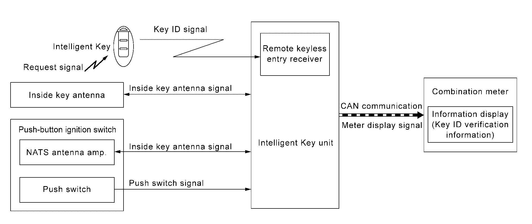
SIGNAL PATH
-
Intelligent Key unit activates inside key antenna and checks that Intelligent Key is in vehicle, when push-button ignition switch operation is performed while ignition switch position is OFF.
-
When Intelligent Key unit does not detect a registered Intelligent Key in Nissan Ariya vehicle, meter display signal is transmitted by Intelligent Key unit to combination meter via CAN communication.
-
When combination meter receives meter display signal, key ID verification information displays.
WARNING/INDICATOR OPERATION CONDITION
When all of the following conditions are satisfied.
-
Ignition switch is OFF position.
-
Push-button ignition switch operation is performed.
-
Registered Intelligent Key is not detected inside the Nissan Ariya vehicle.
WARNING/INDICATOR CANCEL CONDITION
When any of the following conditions are satisfied.
-
After 5 seconds are passed since the key ID verification information is displayed.
-
When Intelligent Key backside is contacted to push-button ignition switch while brake pedal is depressed. And then place ignition switch ON.
-
Registered Intelligent Key is detected inside the Nissan Ariya vehicle.
Take Away Warning (Information Display)
DESIGN/PURPOSE
Information display warns the driver that Intelligent Key is not detected in vehicle.
| Symbol | Message |
|---|---|
|
|
No Key Detected |
SYNCHRONIZATION WITH MASTER WARNING LAMP
Synchronization is applied.
Refer to Master Warning Lamp.
SYNCHRONIZATION WITH WARNING CHIME
Take away warning
Refer to Take Away Warning (Buzzer).
SYSTEM DIAGRAM
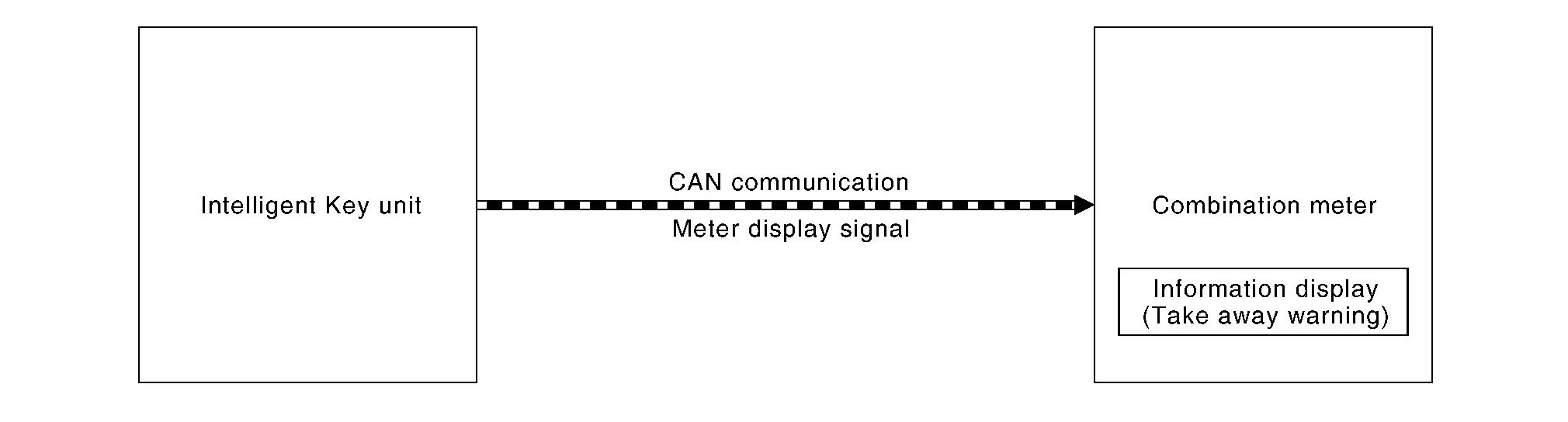
SIGNAL PATH
-
Intelligent Key unit transmits meter display signal to combination meter via CAN communication, when take away warning (buzzer) is operated.
-
When combination meter receives meter display signal, take away warning displays.
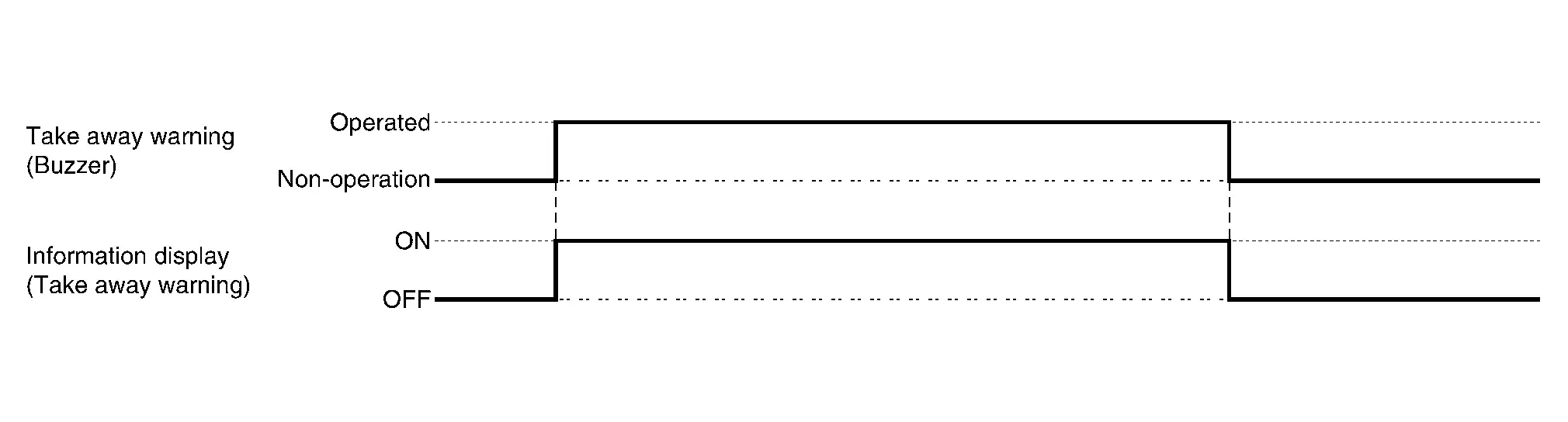
WARNING/INDICATOR OPERATING CONDITION
Take away warning (buzzer) operates.
Refer to Take Away Warning (Buzzer).
WARNING/INDICATOR CANCEL CONDITION
Take away warning (buzzer) is canceled.
Refer to Take Away Warning (Buzzer)
TIMING CHART
Other materials:
Bcm
CONSULT Function (BCM - BCM)
DATA MONITORNOTE:
The following table includes information [items]
inapplicable to this Nissan Ariya vehicle. For information [items]
applicable to this vehicle, refer to CONSULT display items.
Monitor item
[Unit] Description
Door switch assist
[Off/On]
...
System
I-Fcw
System Description
SYSTEM DIAGRAM Component Description
ABS actuator and electric unit (control unit)
ABS Actuator and Electric Unit (Control Unit)
Combination meter (FULL TFT METER)
Combination Meter
Combination meter (7 INCH INFORMATION DISPLAY)
Combination Meter
...
Removal and Installation. Steering Wheel
Exploded View
Steering wheel
: N·m (kg-m, ft-lb)
: Always replace after every disassembly.
Removal and Installation
REMOVALSet vehicle to the straight-ahead position.
Remove driver air bag module. Refer to R ...