Nissan Rogue (T33) 2021-Present OwnerŌĆÖs Manual & User Guide: Fuses
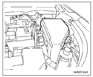
Engine compartment
Basic information
WARNING
Never use fuses with a different amperage rating from what is specified on the fuse box cover. Doing so may damage the electrical system or cause a fire.
If electrical equipment in the Nissan Rogue stops working, inspect the fuses for an open element.
1. Be sure the ignition and headlights are turned off.
2. Open the hood.
3. Remove the fuse/fusible link box cover using a suitable tool and pressing the tab.
4. Locate the fuse that needs replacement.
5. Remove it using the puller from the passenger fuse box.
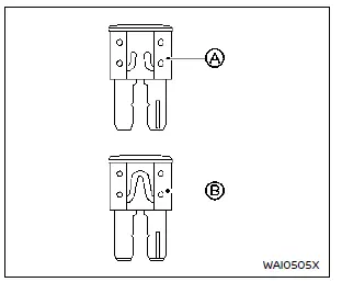
6. If the fuse is open A, replace it with a new fuse B.
7. If the new fuse opens again, have the electrical system inspected by a NISSAN dealer.
Fusible links
If electrical components do not operate and fuses are fine, check the fusible links. Replace only with genuine NISSAN parts. For service, visit a NISSAN dealer.
Passenger compartment
Basic information
WARNING
Never install a fuse with a higher or lower amperage rating than specified. This could damage electronic systems or create a fire hazard.
If any interior electrical feature of the Nissan Rogue fails, check the fuses.
1. Turn off ignition and headlights.
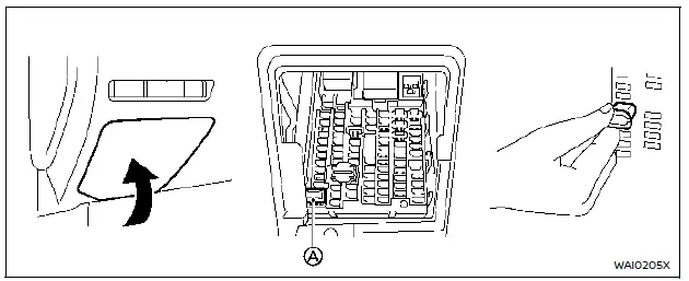
2. Remove the interior fuse box cover.
3. Remove the fuse with the puller A.
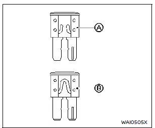
4. If the fuse is open A, replace it with a new fuse B.
5. If the new fuse opens again, professional service is required.
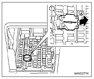
Extended storage switch (if equipped)
This switch is used when the vehicle is being shipped. It is located in the driver-side fuse panel. If electrical functions fail, make sure the extended storage switch is fully pressed into place.
How to put the vehicle into extended storage mode:
1. Start the engine and let it run for over 60 seconds.
2. Remove the fuse box cover.
3. Pinch the locking tabs 1 on the top and bottom of the switch.
4. Pull the switch straight out 2.
5. Turn the engine off.
How to take the vehicle out of extended storage mode:
- Push the extended storage switch fully in.
Other materials:
Basic Inspection. Diagnosis and Repair Work Flow
Work Flow
OVERALL SEQUENCEDETAILED FLOWGET INFORMATION FOR SYMPTOM
Get detailed information from the customer about the symptom (the
condition and the environment when the incident/malfunction occurs).
Check operation condition of the function that is malfunctioning.
>>
G ...
Its Can Communication 3 Circuit
Diagnosis Procedure
CHECK CAN DIAGNOSIS
Check the CAN diagnosis results from CONSULT to see that the ITS CAN
communication 1 circuit and ITS CAN communication 4 circuit have no
malfunction.
Are the ITS CAN communication 1 circuit and ITS CAN communication 4 circuit normal?
YES>>
GO T ...
With Idle Start/stop. Symptom Diagnosis. Charging System
Charging System
Symptom Table
Symptom Reference
Discharged 12V battery
Refer to Work Flow (With EXP-800 NI or GR8-1200 NI) or Work Flow (Without EXP-800 NI or GR8-1200 NI).
The charge warning lamp does not illuminate when the ignition switch is set to ON.
The charge warning lamp ...