Nissan Rogue (T33) 2021-Present Service Manual: Fuel Level Sensor Signal Circuit
Component Function Check
PERFORM COMPONENT FUNCTION CHECK (1)
-
Ignition switch OFF.
-
Disconnect fuel level sensor unit, fuel pump and FPCM (fuel level sensor) (main) harness connector.
-
Connect variable resistor between harness connector terminals located on the Nissan Ariya vehicle side of the fuel level sensor unit.
Fuel level sensor unit, fuel pump and FPCM (fuel level sensor) (main) Connector Terminals B97 1 2 -
Set variable resistor according to the resistance value shown in the following table and place ignition switch ON.
Resistance (ãÎ)*
(Approx.)Fuel gauge indication position
(Approx.)Less than 94.5 Full 140 3/4 186 1/2 232 1/4 255 1/8 More than 278 Empty *: Reference resistance values used when the combination meter judges the indication position of the fuel gauge.
Is the inspection result normal?
YES>>GO TO 2.
NO>>Refer to DiagnosisãProcedure.
PERFORM COMPONENT FUNCTION CHECK (2)
Check the fuel level sensor unit, fuel pump and FPCM (fuel level sensor) (main). Refer to Component Inspection.
Is the inspection result normal?
YES>>Inspection End.
NO>>Replace the fuel level sensor unit, fuel filter and fuel pump assembly. Refer to Removal and Installation.
DiagnosisProcedure
CHECK FUEL LEVEL SENSOR UNIT, FUEL PUMP AND FPCM (FUEL LEVEL SENSOR) (MAIN) CIRCUIT
-
Ignition switch OFF.
-
Disconnect combination meter harness connector and fuel level sensor unit, fuel pump and FPCM (fuel level sensor) (main) harness connector.
-
Check continuity between combination meter harness connector and fuel level sensor unit, fuel pump and FPCM (fuel level sensor) (main) harness connector.
Combination meter Fuel level sensor unit, fuel pump and FPCM (fuel level sensor) (main) Continuity Connector Terminal Connector Terminal M76 35 B97 2 Yes -
Check continuity between combination meter harness connector and ground.
Combination meter Ground Continuity Connector Terminal M76 35 No
Is the inspection result normal?
YES>>GO TO 2.
NO>>Repair harness or connector.
CHECK FUEL LEVEL SENSOR UNIT, FUEL PUMP AND FPCM (FUEL LEVEL SENSOR) (MAIN) GROUND CIRCUIT
-
Check continuity between fuel level sensor unit, fuel pump and FPCM (fuel level sensor) (main) harness connector and combination meter harness connector.
Fuel level sensor unit, fuel pump and FPCM (fuel level sensor) (main) Combination meter Continuity Connector Terminal Connector Terminal B97 1 M76 36 Yes -
Check continuity between fuel level sensor unit, fuel pump and FPCM (fuel level sensor) (main) harness connector and ground.
Fuel level sensor unit, fuel pump and FPCM (fuel level sensor) (main) Ground Continuity Connector Terminal B97 1 No
Is the inspection result normal?
YES>>Replace combination meter. Refer to Removal and Installation.
NO>>Repair harness or connector.
Component Inspection
2WD MODELS
CHECK FUEL LEVEL SENSOR UNIT, FUEL PUMP AND FPCM (FUEL LEVEL SENSOR) (MAIN)
-
Remove the fuel level sensor unit and fuel pump. Refer to Removal and Installation.
-
Check the resistance between fuel level sensor unit and fuel pump.
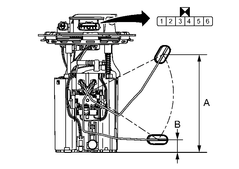
Terminals Condition Resistance (ãÎ)
(Approx.)Height [mm (in)] Fuel level sensor unit and fuel pump 1 2 Full* (A) 91 174.6 (6.87) Empty* (B) 283 22.0 (0.87) *: When float rod is contact with stopper.
Is inspection result normal?
YES>>Inspection End.
NO>>Replace fuel level sensor unit and fuel pump. Refer to Removal and Installation.
AWD MODELS
CHECK FUEL LEVEL SENSOR UNIT AND FUEL PUMP (MAIN)
-
Remove the fuel level sensor unit, fuel pump and FPCM (fuel level sensor) (main). Refer to Removal and Installation.
-
Check the resistance between fuel level sensor unit, fuel pump and FPCM (fuel level sensor) (main).
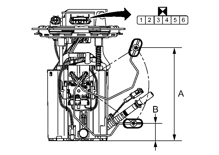
Terminals Condition Resistance (ãÎ)
(Approx.)Height [mm (in)] Fuel level sensor unit and fuel pump (main) 1 2 Full* (A) 28 164.8 (6.49) Empty* (B) 113.5 28.2 (1.11) *: When float rod is contact with stopper.
Is inspection result normal?
YES>>GO TO 2.
NO>>Replace fuel level sensor unit, fuel pump and FPCM (fuel level sensor) (main). Refer to Removal and Installation.
CHECK FUEL LEVEL SENSOR UNIT (SUB)
-
Remove the fuel level sensor unit (sub). Refer to Removal and Installation.
-
Check the resistance between fuel level sensor unit (sub).
*: When float rod is contact with stopper.
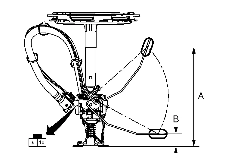
Terminals Condition Resistance (ãÎ)
(Approx.)Height [mm (in)] Fuel level sensor unit (sub) 9 10 Full* (A) 63 185.2 (7.29) Empty* (B) 169.5 19.9 (0.78) *: When float rod is contact with stopper.
Is inspection result normal?
YES>>Inspection End.
NO>>Replace fuel level sensor unit (sub). Refer to Removal and Installation.
Other materials:
Removal and Installation. Electrically-Driven Intelligent Brake Unit
Exploded View
Reservoir cap
Oil strainer
Electrically-driven intelligent brake unit
Clevis
Gasket
: Nôñm (kg-m, ft-lb)
: Always replace after every disassembly.
Removal & Installation
REMOVALCAUTION:
While electrically-driven ...
Entretien gûˋnûˋral
Informations de base
Lors de lãutilisation normale de votre Nissan Rogue, les opûˋrations dãentretien gûˋnûˋral doivent ûˆtre rûˋalisûˋes rûˋguliû´rement et avec rigueur, conformûˋment aux instructions dûˋcrites dans cette section. Toute apparition de bruits anormaux, de vibrations inhabituelle ...
P11b0 Vcr Target Angle (cold Start)
DTC Description
DTC DETECTION LOGIC DTC
CONSULT screen terms
(Trouble diagnosis content)
DTC detection condition
P11B0
00
VCR target angle (cold start)
[Variable compression ratio target angle (cold start)]
Diagnosis condition
Engine cold start
Signal (terminal)
ã ...