Nissan Rogue (T33) 2021-Present Service Manual: Front Wheel Hub and Knuckle
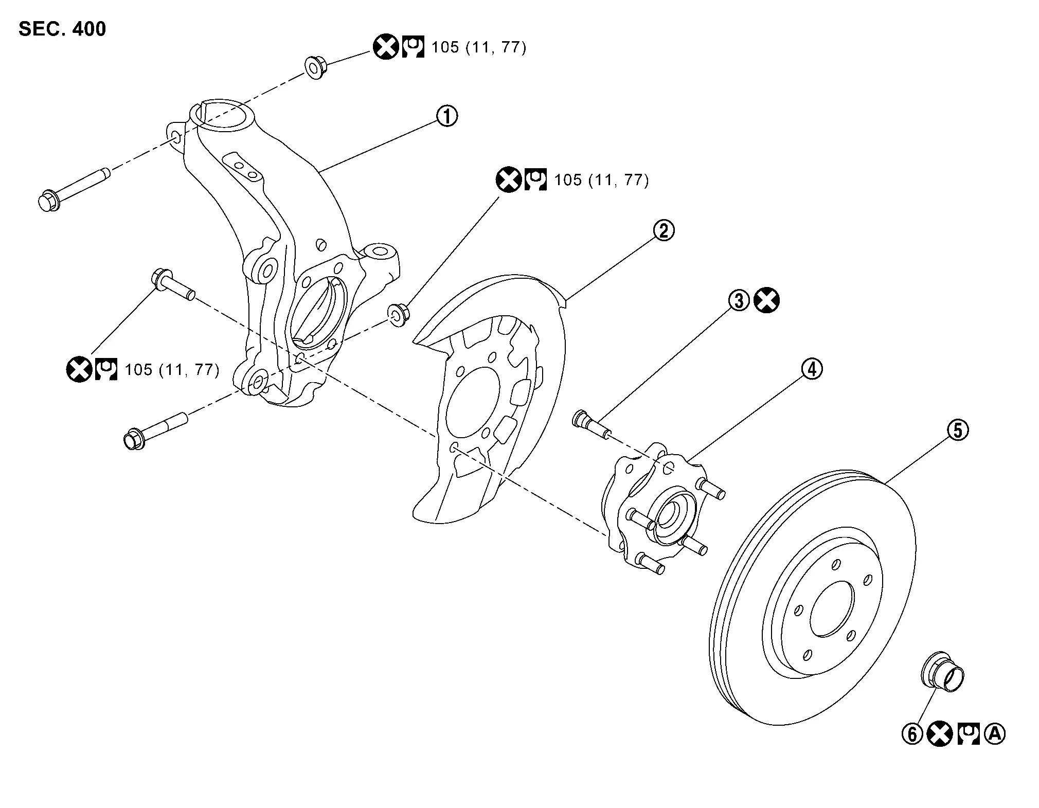
Exploded View
 |
Steering knuckle |  |
Splash guard |  |
Hub bolt |
 |
Wheel hub and bearing assembly |  |
Disc rotor |  |
Wheel hub lock nut |
| A. | : Comply with the installation procedure when tightening. Refer to Removal and Installation. | ||||
 |
: N·m (kg-m, ft-lb) | ||||
 |
: Always replace after every disassembly. | ||||
Removal and Installation
REMOVAL
Remove tires. Refer to Removal & Installation.
Remove front wheel sensor from steering knuckle. Refer to Removal and Installation.
Remove lock plate from strut assembly. Refer to Exploded View.
Remove brake caliper assembly. Hang brake caliper assembly in a place where it will not interfere with work. Refer to Removal and Installation.
CAUTION:
Never depress brake pedal while brake caliper is removed.
Remove disc rotor.
CAUTION:
-
Put matching marks
 on the wheel hub assembly and the disc rotor before removing the disc rotor.
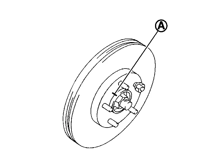
-
Never drop disc rotor.
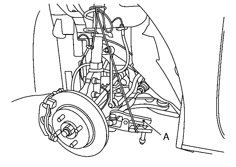
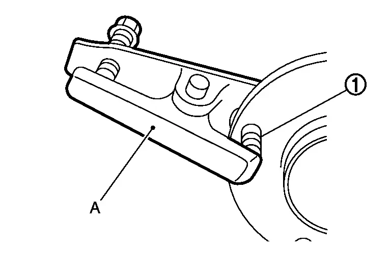
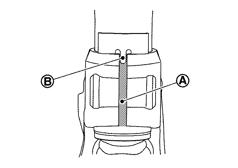
Using suitable tool (A) and Tool (B) release staked area (C) of wheel hub lock nut (D).
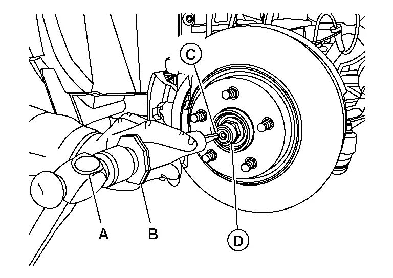
| Tool number (B) | : (NI-52982) |
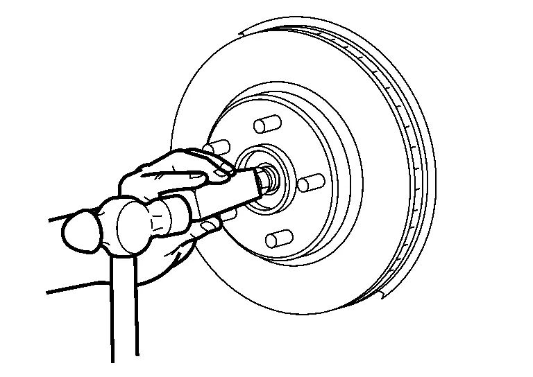
Loosen wheel hub lock nut, using a hub lock nut wrench (SST: KV40104000) (A).

CAUTION:
-
Never use a power tool.
-
When rotation of locknut does not turn smoothly, release stacked area is performed again.
Patch wheel hub lock nut with a piece of wood. Hammer the wood to disengage wheel hub from drive shaft.
CAUTION:
-
Never place drive shaft joint at an extreme angle.
-
Also be careful not to overextend slide joint.
-
Never allow drive shaft to hang down without support for joint sub-assembly, shaft and the other parts.
 NOTE:
NOTE:
Use suitable puller, if wheel hub and drive shaft cannot be separated even after performing the above procedure.
Remove wheel hub lock nut.
Remove wheel hub and bearing assembly and splash guard.
Remove steering outer socket from steering knuckle so as not to damage ball joint boot using a ball joint remover (commercial service tool) (A).
CAUTION:
-
Temporarily tighten the nut to prevent damage to threads and to prevent the ball joint remover from sudden drop turning.
-
Never damage the boot of ball joint.
Remove front stabilizer connecting rod.
Remove transverse link mounting bolts and nuts (lower side).from. Refer to Removal and Installation.
Separate the connection of transverse link and steering knuckle (lower side).
Remove cowl top cover. Refer to Removal and Installation.
Remove front strut assembly and steering knuckle.
Separate the connection of front strut assembly and steering knuckle as follows.
CAUTION:
Be sure to keep the following procedure because steering knuckle may be damaged when you enlarge the gap of steering knuckle too much.
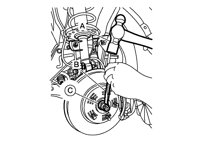
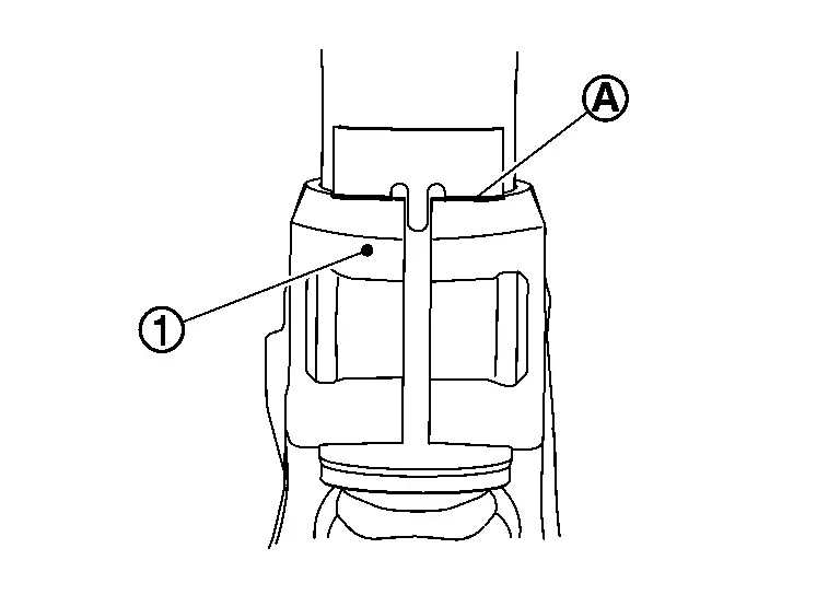
Remove strut mounting bolt and nut from steering knuckle. Measure the gap (A) of the steering knuckle. And then mark the enlarged limit (B) to the chisel.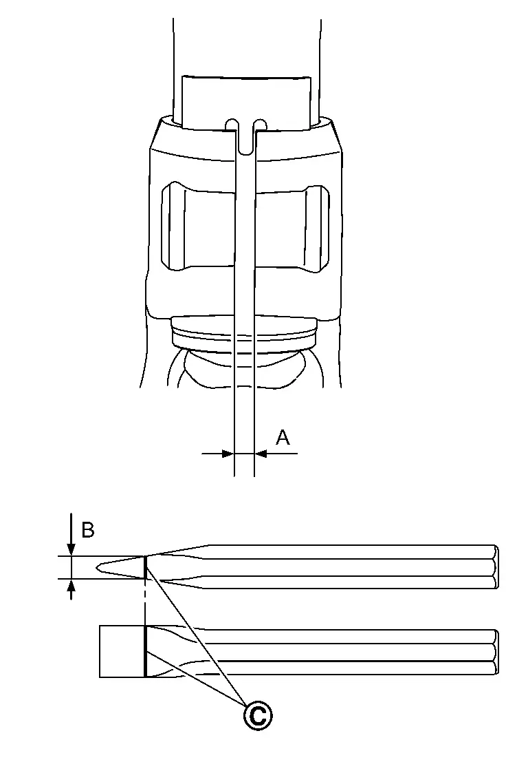
| (C) | Marking |
| Enlarged limit (B) = gap (A) + 2.5 mm (0.098 in) |
NOTE:
Standard of gap: 6.9 ± 0.5 mm (0.272 ± 0.020 in)
Enlarge the gap of the steering knuckle with the chisel (A) (commercial service tool) not to surpass a limit as shown in the figure.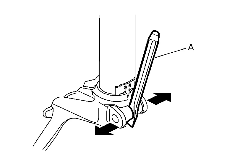
CAUTION:
-
Never enlarge the gap more than 2.5 mm (0.098 in).
-
Be careful not to damage the projection
and strut assembly  with the chisel.
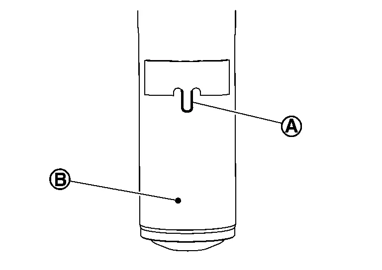
CAUTION:
-
Never place drive shaft joint at an extreme angle.
-
Be careful not to overextend slide joint.
-
Never allow drive shaft to hang down without support for joint sub-assembly, shaft and the other parts.
-
Be sure to remove lubricants if lubricant has been used to separate the connection of strut assembly and steering knuckle.
Remove hub bolts from wheel hub , using the ball joint remover (commercial service tool) (A).
CAUTION:
-
Remove hub bolt only when necessary.
-
Never hammer the hub bolt to avoid impact to the wheel bearing.
-
Pull out the hub bolt in a direction perpendicular to the wheel hub.
Perform inspection after removal. Refer to Inspection.
INSTALLATION
Note the following, and install in the reverse order of the removal.
Hub Bolts
Place a washer as shown in the figure to install the hub bolts by using the tightening force of the nut .
CAUTION:
-
Check that there is no clearance between wheel hub, and hub bolt.
-
Never reuse hub bolt.
Drive shaft
-
Clean the matching surface of wheel hub lock nut and wheel hub.
CAUTION:
Never apply lubricating oil to these matching surface.
-
Clean the matching surface of drive shaft, wheel hub, and wheel bearing. And then apply paste [service parts (440037S000)] to surface
of joint sub-assembly of drive shaft.
CAUTION:
Apply paste to cover entire flat surface of joint sub-assembly of drive shaft.
Amount paste 1.0 – 3.0 g (0.04 – 0.10 oz) -
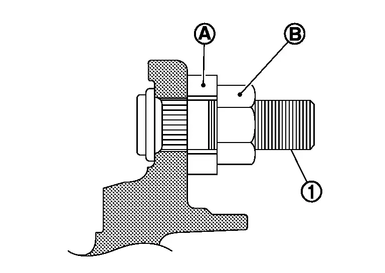
When installing drive shaft to wheel hub.
CAUTION:
Never overlap drive shaft stacked area
and hub bolts .
-
Use the following torque range for tightening the wheel hub lock nut.
: 255 N·m (26 kg-m, 188 ft-lb) CAUTION:
-
Since the drive shaft is assembled by press-fitting, use the tightening torque range for the wheel hub lock nut.
-
Be sure to use torque wrench to tighten the wheel hub lock nut. Never use a power tool.
-
Never reuse wheel hub lock nut.
NOTE:
Wheel hub lock nut tightening torque does not over torque for avoiding axle noise, and does not less than torque for avoiding looseness.
-
-
Using suitable tool (A) and cold chisel (B) stake the wheel hub lock nut (C) as shown.
WARNING:
To avoid the risk of death or severe personal injury:
-
Use the following range when staking the wheel hub lock nut.
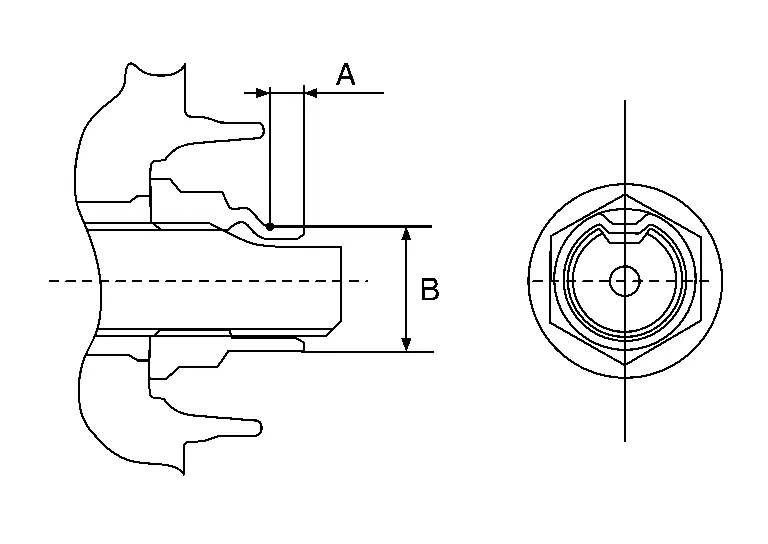
(A) : 6.2 mm (0.244 in) (B) : 26.4 - 27.8 mm (1.039 - 1.094 in) -
Disc rotor
CAUTION:
-
Align the matching marks
made during removal when reusing the disc rotor. -
Never drop disc rotor.
Strut Assembly and Steering Knuckle Connection
CAUTION:
Be sure to remove lubricants if lubricant has been used to separate the connection of strut assembly and steering knuckle.
Install the steering knuckle to strut assembly as follows.
Set suitable jack under steering knuckle.
Align the gap of steering knuckle to the projection part of strut.
Tighten the mounting bolt and nut with pushing up the steering knuckle  until contacts stopper bracket end face, using a suitable jack.
CAUTION:
Check the stable condition when using a jack.
Inspection
INSPECTION AFTER REMOVAL
Check the following items, and replace the part if necessary.
-
Check components for deformation, cracks, and other damage.
-
Check boots of transverse link and steering outer socket ball joint for breakage, axial end play, and swing torque.
-
Transverse link: Refer to Inspection.
-
Steering outer socket: Refer to Inspection.
-
INSPECTION AFTER INSTALLATION
Check runout of disc rotor, when replaced the disc rotor. Refer to Inspection and Adjustment.
Check wheel sensor harness for proper connection. Refer to Exploded View.
Check the wheel alignment. Refer to Inspection.
Adjust neutral position of steering angle sensor. Refer to Work Procedure.
Other materials:
Dtc/circuit Diagnosis. B2426-25 Spindle Sensor Lh
DTC Description
DTC DETECTION LOGIC DTC No.
CONSULT screen items
(Trouble diagnosis content) DTC Detection Condition
B2426-25
Spindle sensor LH
(Spindle sensor left hand)
Diagnosis condition
When automatic back door open/close function operate
Signal (terminal)
Encoder LH ...
Basic information
The Nissan Rogue offers several Driver Assistance features that support the driver in different situations. Availability depends on vehicle equipment.
Forward Driving Aids
Automatic Emergency Braking (AEB) with Pedestrian Detection
Provides alerts and braking assistance when a forward collisi ...
Informations de base
AVERTISSEMENT
Le non-respect des instructions et avertissements relatifs à l'utilisation correcte du système de freinage d'urgence automatique avec détection des piétons du Nissan Rogue peut entraîner des blessures graves, voire mortelles.
Le système de freinage d'urgence automatique avec ...