
Nissan Rogue (T33) 2021-Present Service Manual: B12a4u201392 Battery Current Sensor
DTC Description
DTC DETECTION LOGIC
| DTC No. | CONSULT screen items | DTC Detection Condition | ||
|---|---|---|---|---|
| (Trouble diagnosis content) | [Malfunction type] | |||
| B12A4–92 |
BATTERY CURRENT SENSOR (Battery current sensor) |
[PFM/INCORR ECT OPERATN] | Diagnosis condition | When ignition switch is ON. |
| Signal (terminal) | LIN (BAT CURRENT SEN) | |||
| Threshold | 12V battery current sensor internal malfunction (current). | |||
| Diagnosis delay time | 1 second or less | |||
POSSIBLE CAUSE
-
IPDM E/R
-
12V battery current sensor (With 12V battery temperature sensor)
FAIL-SAFE
Fix the power generation command value to 14.3 V.
DTC CONFIRMATION PROCEDURE
PERFORM COMPONENT FUNCTION CHECK
 CONSULT
-
Start engine and wait for 10 seconds or more.
-
Select “Self diagnosis result� mode of “IPDM E/R�.
Is the inspection result normal?
YES-1>>To check malfunction symptom before repair: Refer to Intermittent Incident.
YES-2>>Confirmation after repair: Inspection End.
NO>>Proceed to Diagnosis Procedure.
Diagnosis Procedure
CHECK LIN COMMUNICATION SIGNAL
-
Ignition switch ON.
-
Check signal between 12V battery current sensor harness connector and ground using an oscilloscope.
(+) (−) Signal 12V battery current sensor Connector Terminal E37 2 Ground 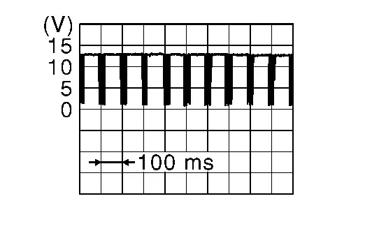
Is the inspection result normal?
YES>>Replace IPDM E/R. Refer to Removal and Installation.
NO>>Replace 12V battery current sensor. Refer to Removal and Installation.
Other materials:
Led Headlamp. Wiring Diagram
Headlamp
Wiring Diagram
Refer to Wiring Diagram.
Daytime Running Light System
Wiring Diagram
Refer to Wiring Diagram.
Intelligent Auto Light System-With Type a Meter
Wiring Diagram
Refer to Wiring Diagram.
Intelligent Auto Light System-With Type B Meter
Wiring Diagram
Refer to Wiring Diagram.
T ...
P1c91-14 Sub Starter & Generator
DTC Description
DTC DETECTION LOGIC DTC No. CONSULT screen terms (Trouble diagnosis content) DTC detection condition
P1C91-14
Sub starter & generator
(Sub starter & generator)
Diagnosis condition
Engine running at idle
Signal (terminal)
Battery voltage
Threshold ...
Brake fluid
For more information on brake fluid type and capacity, refer to “Capacities and recommended fluids/lubricants�.
WARNING
Always use new brake fluid from a sealed container. Contaminated, old, or poor-quality fluid may damage the brake system and reduce stopping performance.
Clean the filler c ...