Nissan Rogue (T33) 2021-Present Service Manual: B12a4-81 Battery Current Sensor
DTC Description
DTC DETECTION LOGIC
| DTC No. | CONSULT screen items | DTC Detection Condition | ||
|---|---|---|---|---|
| (Trouble diagnosis content) | [Malfunction type] | |||
| B12A4ŌĆō81 |
BATTERY CURRENT SENSOR (Battery current sensor) |
[INVALID SERIAL DATA RECEIVED] | Diagnosis condition | When ignition switch is ON. |
| Signal (terminal) | LIN (BAT CURRENT SEN) | |||
| Threshold | 12V battery current sensor and IPDM E/R cannot communicate with LIN communication signal. | |||
| Diagnosis delay time | 2 seconds or more | |||
POSSIBLE CAUSE
-
12V battery terminal is not connected
-
Harness or connectors
-
12V battery current sensor (With 12V battery temperature sensor)
-
IPDM E/R
FAIL-SAFE
Fix the power generation command value to 14.3 V.
DTC CONFIRMATION PROCEDURE
PERFORM COMPONENT FUNCTION CHECK
 CONSULT
-
Start engine and wait for 10 seconds or more.
-
Select ŌĆ£Self diagnosis resultŌĆØ mode of ŌĆ£IPDM E/RŌĆØ.
Is the inspection result normal?
YES-1>>To check malfunction symptom before repair: Refer to Intermittent Incident.
YES-2>>Confirmation after repair: Inspection End.
NO>>Proceed to Diagnosis Procedure.
Diagnosis Procedure
CHECK LIN COMMUNICATION SIGNAL 1
CONSULT DATA MONITOR
Select ŌĆ£Battery current sen value (LIN)ŌĆØ of ŌĆ£IPDM E/RŌĆØ data monitor item.
| Monitor item | Condition | Monitor status |
|---|---|---|
| Battery current sen value (LIN) |
Engine running
|
(ŌĆō200.00) ŌĆō (+300.00) A |
Is the inspection result normal?
YES>>GO TO 2.
NO>>Replace IPDM E/R. Refer to Removal and Installation.
CHECK FUSE
-
Ignition switch OFF.
-
Check that the following fuse is not blown (open).
No. Capacity 89 10A
Is the fuse blown (open)?
YES>>Replace the blown (open) fuse after repairing the cause of blown (open).
NO>>GO TO 3.
CHECK 12V BATTERY CURRENT SENSOR POWER
-
Disconnect 12V battery current sensor connector.
-
Ignition switch ON.
-
Check the voltage between 12V battery current sensor harness connector and ground.
(+) (-) Voltage (V) 12V battery current sensor Connector Terminal E37 1 Ground 12V battery voltage
Is the inspection result normal?
YES>>GO TO 4.
NO>>Repair or replace harness.
CHECK LIN COMMUNICATION SIGNAL
-
Ignition switch ON.
-
Check signal between 12V battery current sensor harness connector and ground using an oscilloscope.
(+) (ŌłÆ) Signal 12V battery current sensor Connector Terminal E37 2 Ground 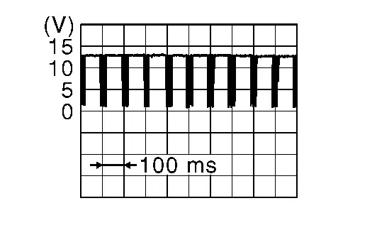
Is the inspection result normal?
YES>>Repair or replace harness.
NO>>Replace 12V battery current sensor. Refer to Removal and Installation.
Other materials:
Turbocharger Boost Sensor
Component Inspection
CHECK TURBOCHARGER BOOST SENSOR
Turn ignition switch OFF.
Remove turbocharger boost sensor with its harness connector.
Install pressure pump (A) to turbocharger boost sensor (1).
CAUTION:
When insert a pressure pump hose to the sensor, be careful to the damag ...
Si├©ges, ceintures de s├®curit├® et syst├©mes de retenue suppl├®mentaires (SRS)
Dans le Nissan Rogue, la s├®curit├® des occupants repose sur lŌĆÖassociation des ceintures, des appuie-t├¬te et des dispositifs SRS (airbags et capteurs). Reportez-vous toujours aux avertissements du manuel avant toute intervention sur un composant SRS.
Airbags avant : protection frontale du ...
Rear View Monitor. Removal and Installation. Rear View Camera
Rear View Camera
Removal and Installation
REMOVALRemove the back door inner finisher. Refer to Removal and Installation.
Remove the rear view camera mounting bolts , And then push the pawls in the direction of the arrow in the figure to remove the rear view camera.
INSTALLATIONInstallation is ...