Nissan Rogue (T33) 2021-Present Service Manual: Propilot Assist 2.1 :: Ecu Diagnosis Information
Adas Control Unit 2
List of ECU Reference
| ECU | Reference |
|---|---|
| ADAS control unit 2 | Reference Value |
| Fail-safe (ADAS Control Unit) | |
| DTC Inspection Priority Chart | |
| DTC Index |
Distance Sensor
List of ECU Reference
| ECU | Reference |
|---|---|
| Distance sensor | Reference Value |
| Fail-safe | |
| DTC Inspection Priority Chart | |
| DTC Index |
Front Camera Unit
List of ECU Reference
| ECU | Reference |
|---|---|
| Front camera unit | Reference Value |
| Fail-safe | |
| DTC Inspection Priority Chart | |
| DTC Index |
Hd Map Module
Reference Value
Values On The Diagnosis Tool
 NOTE:
NOTE:
The following table includes information (items) inapplicable to this Nissan Ariya vehicle. For information (items) applicable to this vehicle, refer to CONSULT display items.
| Monitor item | Condition | Value/Status | |
|---|---|---|---|
| Mileage | Ignition SW ON | Almost the same value as odometer | |
| Nissan Ariya Vehicle Speed | Driving | Almost the same value as speedometer | |
| Shift position | Ignition SW ON | Displays shift position | |
| Ignition | Ignition SW OFF | OFF | |
| Ignition SW ACC | ACC | ||
| Ignition SW ON | IGN | ||
| While checking status of ignition SW ON | Under checking | ||
| G sensor initial learn value (X) | Ignition SW ON | (ŌĆō0.1005)-(0.0847)G | |
| G sensor initial learn value (Y) | Ignition SW ON | (ŌĆō0.1005)-(0.0847)G | |
| G sensor initial learn value (Z) | Ignition SW ON | (ŌĆō0.9003)-(1.0996)G | |
| IMU sensor temperature | Ignition SW ON | (ŌĆō40.0)-(85.0)Ōäā | |
| Gyro current value X | Ignition SW ON | (ŌĆō124.8780)-(124.8742)deg/s | |
| Gyro current value Y | Ignition SW ON | (ŌĆō124.8780)-(124.8742)deg/s | |
| Gyro current value Z | Ignition SW ON | (ŌĆō124.8780)-(124.8742)deg/s | |
| Gyro offset learning value (X) | Ignition SW ON | (ŌĆō124.8780)-(124.8742)deg/s | |
| Gyro offset learning value (Y) | Ignition SW ON | (ŌĆō124.8780)-(124.8742)deg/s | |
| Gyro offset learning value (Z) | Ignition SW ON | (ŌĆō124.8780)-(124.8742)deg/s | |
| Gyro sensitv corret learn value | Ignition SW ON | 0.0000 - 2.0000 | |
| G sensor pitch correct value | Ignition SW ON | (ŌĆō50.0000)-(50.0000)% | |
| GPS positioning status | Ignition SW ON with radio wave | GPS signal cannot be received | Non-positioning |
| When information is received from three satellites and the position can be measured on a plane | 2D positioning | ||
| When information is received from four or more satellites and accurate self-position measurement is possible | 3D positioning | ||
| When the number of satellites is small or when only UTC (Universal Coordinated Time) can be confirmed due to information block | Time | ||
| GPS position info (Latitude) | Ignition SW ON with radio wave | (ŌĆō90.0000)-(90.0000) | |
| GPS position info (Longitude) | Ignition SW ON with radio wave | (ŌĆō180.0000)-(180.0000) | |
| GPS position info (Ellipsoid) | Ignition SW ON with radio wave | (ŌĆō8000.000)-(8000.000)mm | |
| GPS position info (Geoid) | Ignition SW ON with radio wave | (ŌĆō8000.000)-(8000.000)mm | |
| GPS speed info (Vhicle speed) | Ignition SW ON with radio wave | 0.0000 - 100000.0000 mm/s | |
| GPS azimuth info | Ignition SW ON with radio wave | 0.0000 - 2.0000 deg | |
| Nissan Ariya Vehicle speed correction value | Ignition SW ON | 0.0000 - 2.0000 | |
| Power supply voltage | Ignition SW ON | 7 - 16 V | |
| Map update progress (USB) |
The item is displayed, but it is not used |
ŌĆö | |
| Map update license | Ignition SW ON | When the customer has a HD map license (not expired) and radio wave is available | Valid |
| Except the above | Not valid | ||
| license expiration date | Ignition SW ON | 1 - 31 | |
| License expiration month | Ignition SW ON | 1 - 12 | |
| USB connection status |
The item is displayed, but it is not used |
ŌĆö | |
| Map update status (Data type) |
The item is displayed, but it is not used |
ŌĆö | |
| G sensor learning value X | Ignition SW ON | (ŌĆō2.0000)-(2.0000)G | |
| ŃĆĆ G sensor learning value Y ŃĆĆ | Ignition SW ON | (ŌĆō2.0000)-(2.0000)G | |
| G sensor learning value Z ŃĆĆ | Ignition SW ON | (ŌĆō2.0000)-(2.0000)G | |
| ŃĆĆ Gyro offset initial learn value X ŃĆĆ | Ignition SW ON | (ŌĆō124.9980)-(124.9942)deg/s | |
| ŃĆĆ Gyro offset initial learn value Y ŃĆĆ | Ignition SW ON | (ŌĆō124.9980)-(124.9942)deg/s | |
| ŃĆĆ Gyro offset initial learn value Z ŃĆĆ | Ignition SW ON | (ŌĆō124.9980)-(124.9942)deg/s | |
| ŃĆĆ ECU instll ang lrn ltst val Roll ŃĆĆ | Ignition SW ON | (ŌĆō180.0)-(180.0)deg | |
| ŃĆĆ ECU instll ang lrn ltst val Pitch ŃĆĆ | Ignition SW ON | (ŌĆō180.0)-(180.0)deg | |
| ŃĆĆ Intrnl area 1 prog update cntr ŃĆĆ | Ignition SW ON | 0.0000 - 4294967295 [count] | |
| ŃĆĆ Intrnl area 2 prog update cntr ŃĆĆ | Ignition SW ON | 0.0000 - 4294967295 [count] | |
| ŃĆĆ Intrnl area 3 prog update cntr ŃĆĆŃĆĆ | Ignition SW ON | 0.0000 - 4294967295 [count] | |
| ŃĆĆ Intrnl area 4 prog update cntr ŃĆĆ | Ignition SW ON | 0.0000 - 4294967295 [count] | |
| ŃĆĆ ECU instll angle learn val Roll ŃĆĆ | Ignition SW ON | (ŌĆō180.0)-(180.0)deg | |
| ECU instll angle learn val Pitch | Ignition SW ON | (ŌĆō180.0)-(180.0)deg | |
| ŃĆĆ Intrnl area 5 prog update cntr ŃĆĆ | Ignition SW ON | 0.0000 - 4294967295 [count] | |
| FOTA status | Ignition SW ON | When waiting | Waiting |
| When receiving software | Receiving | ||
| When copying software | Copying | ||
| When checking Nissan Ariya vehicle condition | Checking vehicle condition | ||
| When preparing communication | Preparing to start | ||
| When switching software | Switching | ||
| When restarting HD map module | Restarting | ||
| When checking the received software version | Checking version | ||
| When updating software | Under configuration | ||
| When software update is completed | Operation end | ||
| When an error is detected other than during software update | Error 1 | ||
| When cancelling software update | Cancelling | ||
| When an error is detected during software update | Error 2 | ||
| When repairing an error | Repairing | ||
| When error repair is complete | Repair end | ||
| FOTA cancel counter | Ignition SW ON | 0 - 255 | |
Terminal Layout
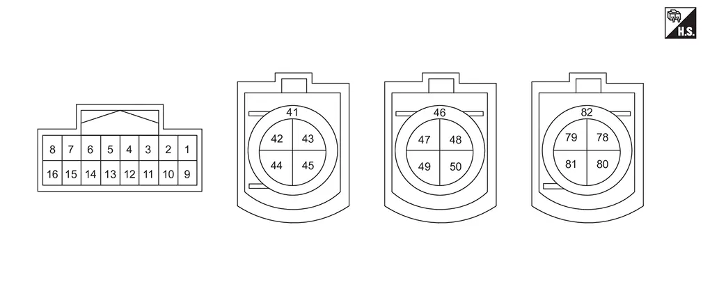
Physical Values
|
Terminal No. (Wire color) | Description | Condition |
Value (Approx.) | |||
|---|---|---|---|---|---|---|
| + | ŌĆō | Signal name | Input/Output | |||
|
1 (LA/B) |
Ground | Ground | ŌĆö | Ignition SW ON | 0 V | |
|
3 (LA/G) |
’╝æ (LA/B) |
Ignition power supply | Input | Ignition SW ON | Battery voltage | |
|
13 (LA/Y) |
’╝æ (LA/B) |
Battery power supply | ŌĆö | Ignition SW ON | Battery voltage | |
|
16 (LA/B) |
Ground | Ground | ŌĆö | Ignition SW ON | 0 V | |
|
41 (SHIELD) |
ŌĆö | Shield | ŌĆö | ŌĆö | ŌĆö | |
|
44 (Y) |
Ethernet(+) | ŌĆö | ŌĆö | ŌĆö | ||
|
45 (G) |
Ethernet(-) | ŌĆö | ŌĆö | ŌĆö | ||
|
46 (SHIELD) |
Shield | ŌĆö | ŌĆö | ŌĆö | ||
|
49 (Y) |
Ethernet(+) | ŌĆö | ŌĆö | ŌĆö | ||
|
50 (G) |
Ethernet(-) | ŌĆö | ŌĆö | ŌĆö | ||
|
80 (Y) |
Ethernet(+) | ŌĆö | ŌĆö | ŌĆö | ||
|
81 (G) |
Ethernet(-) | ŌĆö | ŌĆö | ŌĆö | ||
|
82 (SHIELD) |
Shield | ŌĆö | ŌĆö | ŌĆö | ||
Fail-safe
Refer to Fail-safe (HD Map Module).
DTC Inspection Priority Chart
If multiple DTCs are detected simultaneously, check them one by one depending on the following DTC inspection priority chart.
| Priority | Detected items (DTC) | |
|---|---|---|
| 1 |
|
|
| 2 |
|
|
DTC Index
Self Diagnostic Result ├Ś: Applicable
| DTC | CONSULT display | Fail-safe | Reference | |||
|---|---|---|---|---|---|---|
| Lane keeping function * | Lane change support function | Overtaking support function | ||||
| B14A0 | 45 | Control module | ├Ś | ├Ś | ├Ś | Refer to DTC Description. |
| 49 | ├Ś | ├Ś | ├Ś | Refer to DTC Description. | ||
| 4B | ├Ś | ├Ś | ├Ś | Refer to DTC Description. | ||
| B14A1 | A2 | Battery voltage | ├Ś | ├Ś | ├Ś | Refer to DTC Description. |
| A3 | ├Ś | ├Ś | ├Ś | Refer to DTC Description. | ||
| B14A3 | 19 | USB memory data | - | - | - | Refer to DTC Description. |
| B14A4 | 11 | GPS antenna | ├Ś | ├Ś | ├Ś | Refer to DTC Description. |
| 13 | ├Ś | ├Ś | ├Ś | Refer to DTC Description. | ||
| B14A5 | 45 | HD map data error 1 | ├Ś | ├Ś | ├Ś | Refer to DTC Description. |
| B14AD | 54 | G sensor calibration incomplete | - | - | - | Refer to DTC Description. |
| B14B0 | 56 | Nissan Ariya Vehicle Identification Number data mismatch | ├Ś | ├Ś | ├Ś | Refer to DTC Description. |
| B14B4 | 11 | L band antenna | ├Ś | ├Ś | ├Ś | Refer to DTC Description. |
| 13 | ├Ś | ├Ś | ├Ś | Refer to DTC Description. | ||
| U1C93 | 86 | GPS communication error | ├Ś | ├Ś | ├Ś | Refer to DTC Description. |
| 87 | ├Ś | ├Ś | ├Ś | Refer to DTC Description. | ||
| U1C96 | 82 | Ethernet communication error | - | - | - | Refer to DTC Description. |
| 87 | - | - | - | Refer to DTC Description. | ||
| U1C97 | 82 | ├Ś | ├Ś | ├Ś | Refer to DTC Description. | |
| 83 | ├Ś | ├Ś | ├Ś | Refer to DTC Description. | ||
| U1C98 | 82 | ├Ś | ├Ś | ├Ś | Refer to DTC Description. | |
| 87 | ├Ś | ├Ś | ├Ś | Refer to DTC Description. | ||
| U27A9 | 88 | ├Ś | ├Ś | ├Ś | Refer to DTC Description. | |
| U28A9 | 88 | ├Ś | ├Ś | ├Ś | Refer to DTC Description. | |
| U29A9 | 88 | ├Ś | ├Ś | ├Ś | Refer to DTC Description. | |
*: ProPILOT Assist 2.1 display is blue
Power Network Separate Relay
Reference Value
Values On The Diagnosis Tool
NOTE:
The following table includes information (items) inapplicable to this Nissan Ariya vehicle. For information (items) applicable to this vehicle, refer to CONSULT display items.
| Monitor item | Condition | Value/Status | |
|---|---|---|---|
| Nissan Ariya Vehicle Speed | Driving | Almost the same value as speedometer | |
Terminal Layout
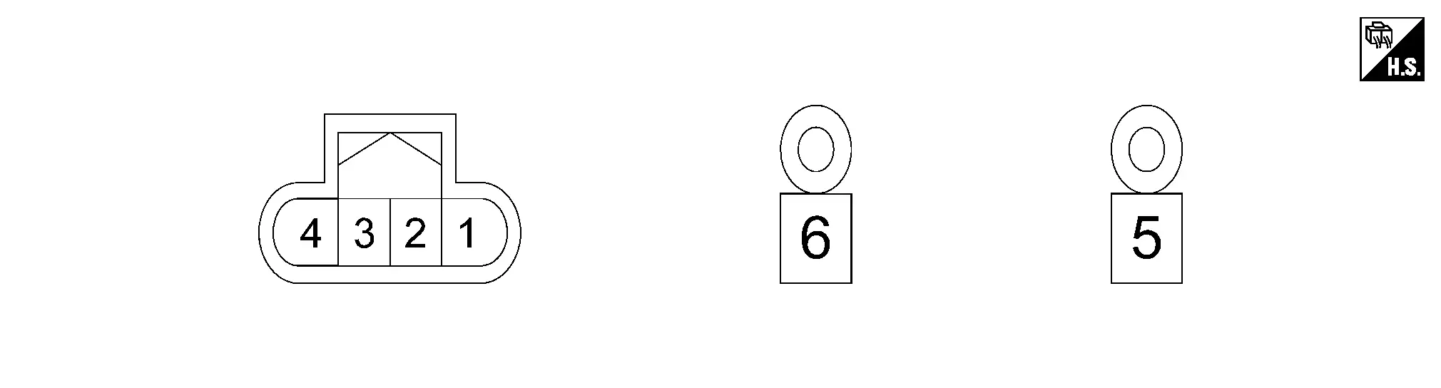
Physical Values
|
Terminal No. (Wire color) | Description | Condition |
Value (Approx.) | |||
|---|---|---|---|---|---|---|
| + | ŌĆō | Signal name | Input/Output | |||
|
1 (LA/B) |
Ground | Ground | ŌĆö | ŌĆö | ŌĆö | |
|
2 (GR) |
ŌĆö | CAN communication-H | ŌĆö | ŌĆö | ŌĆö | |
|
3 (V) |
CAN communication-L | ŌĆö | ŌĆö | ŌĆö | ||
|
4 (LA/GR) |
1 (LA/B) |
Ignition power supply | Input | Ignition SW ON | Battery voltage | |
Fail-safe
Refer to Fail-safe (Power Network Separate Relay).
DTC Inspection Priority Chart
If multiple DTCs are detected simultaneously, check them one by one depending on the following DTC inspection priority chart.
| Priority | Detected items (DTC) | |
|---|---|---|
| 1 |
|
|
| 2 | B23C0-04: Power network separate relay | |
DTC Index
Self Diagnostic Result ├Ś: Applicable
| DTC | CONSULT display | Fail-safe | Reference | |||||
|---|---|---|---|---|---|---|---|---|
| Nissan Ariya Vehicle speed/vehicle-to-vehicle distance control mode function | Lane keeping function *1 | Lane keeping function *2 | Lane change support function | Overtaking support function | ||||
| B23C0 | 04 | Power network separate relay | ├Ś | ├Ś | ├Ś | ├Ś | ├Ś | Refer to DTC Description. |
| U2148 | 87 | CAN comm err (brake control unit) | ├Ś | ├Ś | ├Ś | ├Ś | ├Ś | Refer to DTC Description. |
| U214F | 87 | CAN comm err (BCM) | ├Ś | ├Ś | ├Ś | ├Ś | ├Ś | Refer to DTC Description. |
| U2152 | 87 | CAN communication error advanced driver assistant systems control unit | ├Ś | ├Ś | ├Ś | ├Ś | ├Ś | Refer to DTC Description. |
| U215B | 87 | CAN comm err (IPDM E/R) | ├Ś | ├Ś | ├Ś | ├Ś | ├Ś | Refer to DTC Description. |
| U2175 | 87 | CAN communication error (AVM) | ├Ś | ├Ś | ├Ś | ├Ś | ├Ś | Refer to DTC Description. |
| U2176 | 87 | CAN communication error (chassis control module/steering angle sensor) | ├Ś | ├Ś | ├Ś | ├Ś | ├Ś | Refer to DTC Description. |
| U2A0B | 88 | Communication Bus Off CH2-CAN | ├Ś | ├Ś | ├Ś | ├Ś | ├Ś | Refer to DTC Description. |
Driver Monitor Camera Control Unit
List of ECU Reference
| ECU | Reference |
|---|---|
| Driver monitor camera control unit | Reference Value |
| Fail-safe (Driver Monitor Camera Control Unit) | |
| DTC Inspection Priority Chart | |
| DTC Index |
Side Radar Front Lh
List of ECU Reference
| ECU | Reference |
|---|---|
| Side radar front LH | Reference Value |
| Fail-safe (Side Radar) | |
| DTC Inspection Priority Chart | |
| DTC Index |
Side Radar Front Rh
List of ECU Reference
| ECU | Reference |
|---|---|
| Side radar front RH | Reference Value |
| Fail-safe (Side Radar) | |
| DTC Inspection Priority Chart | |
| DTC Index |
Side Radar Rear Lh
List of ECU Reference
| ECU | Reference |
|---|---|
| Side radar rear LH | Reference Value |
| Fail-safe (Side Radar) | |
| DTC Inspection Priority Chart | |
| DTC Index |
Side Radar Rear Rh
List of ECU Reference
| ECU | Reference |
|---|---|
| Side radar rear RH | Reference Value |
| Fail-safe (Side Radar) | |
| DTC Inspection Priority Chart | |
| DTC Index |
Other materials:
Dtc/circuit Diagnosis. Drive Mode Select Switch Circuit
Diagnosis Procedure
CHECK DRIVE MODE SELECT SWITCH SIGNAL CIRCUIT
Ignition switch OFF.
Disconnect drive mode select switch harness connector and BCM harness connector.
Check the continuity between drive mode select switch harness connector and BCM harness connector.
2WD models with ...
Writing of Calibration Data
Work Procedure
DESCRIPTIONIf only the around view monitor control unit
is replaced, the calibration data stored in the camera can be written
to the around view monitor control unit by selecting "Camera
Calibration" of "Work Support" mode in CONSULT.WORK PROCEDUREWRITE CALIBRATION DATA
With C ...
P0011 Ivt Control
DTC Description
DTC DETECTION LOGIC DTC
CONSULT screen terms
(Trouble diagnosis content)
DTC detection condition
P0011
00
INT/V TIM CONT-B1
(ŌĆ£AŌĆØ Camshaft position - timing over-advanced or system performance bank 1)
Diagnosis condition
Engine running
Signal (term ...