Nissan Rogue (T33) 2021-Present Service Manual: Evap Canister Vent Control Valve
Component Inspection
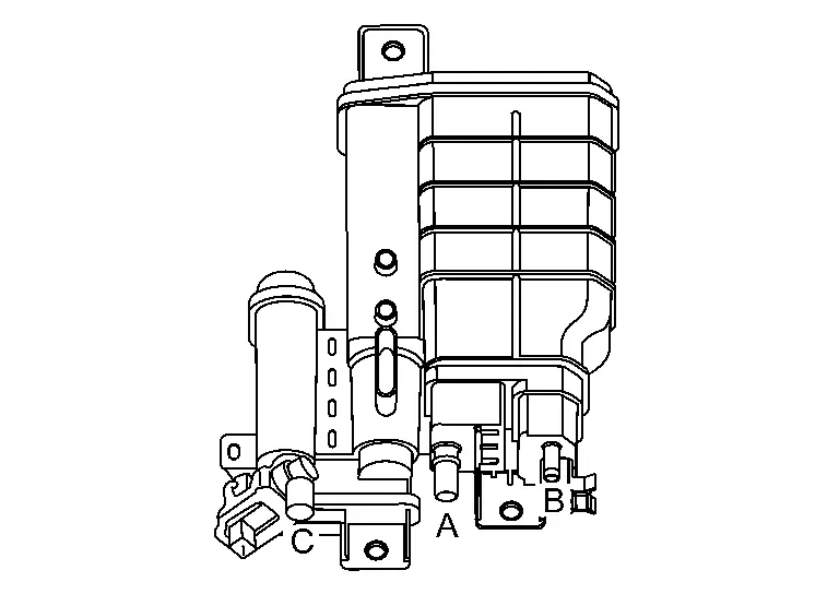
CHECK EVAP CANISTER VENT CONTROL VALVE-1
-
Disconnect hose from (A), (B), and (C) with remaining harness connector connected.
-
Block port (B).
-
Blow air into port (A) and check that it flows freely out of port (C).
Is sufficient air flowed from port (C)?
YES>>GO TO 2.
NO>>Replace EVAP canister vent control valve. Refer to Removal and Installation.
CHECK EVAP CANISTER VENT CONTROL VALVE-2
 With CONSULT
-
Turn ignition switch ON.
-
Perform “VENT CONTROL/V” in “ACTIVE TEST” mode of “ENGINE” using CONSULT.
-
Block port (B).
-
Blow air into port (A) and check that where is leakage point of air.
Where is leakage point?
Port (C)>>Replace EVAP canister vent control valve. Refer to Removal and Installation.
Between EVAP canister vent control valve and EVAP canister >>GO TO 3.
NO air leakage>>INSPECTION END
CHECK EVAP CANISTER VENT CONTROL VALVE-3
Visually check connection portion between EVAP canister vent control valve and EVAP canister for cracks and damage.
Is the inspection result normal?
YES>>Replace EVAP canister and EVAP canister vent control valve. Refer to Removal and Installation.
NO>>Replace EVAP canister. Refer to Removal and Installation.
Other materials:
Component Parts
Automatic Air Conditioning System
Component Parts Location
A.
Instrument panel
B.
Left front of Nissan Ariya vehicle
C.
Right side of blower unit assembly
D.
Right side of heater and cooling unit assembly
E.
Left side of heater and cooling unit assembly
...
B2e08-01 Microphone
DTC Description
DTC DETECTION LOGIC DTC No.
CONSULT screen terms
(Trouble diagnosis content) DTC detection condition
B2E08–01
Microphone
(Microphone)
1
Diagnosis condition
When ignition switch is ON.
Signal (terminal)
Microphone signal
Threshold
7.2 V or more ...
Kr15ddt. Symptom Diagnosis
Heater and Air Conditioning System Symptoms
Symptom Table
SYMPTOM TABLE Symptom Reference Page
A/C system does not come on.
Go to Trouble Diagnosis Procedure for A/C System.
Refer to Diagnosis Procedure (with automatic air
conditioning system) or Diagnosis Procedure (with manual air
...