Nissan Rogue (T33) 2021-Present Service Manual: Engine :: Starting System
Precaution :: Precautions
Precaution for Supplemental Restraint System (SRS) "AIR BAG" and "SEAT BELT PRE-TENSIONER"
The Supplemental Restraint System such as ŌĆ£AIR BAGŌĆØ and ŌĆ£SEAT BELT PRE-TENSIONERŌĆØ, used along with a front seat belt, helps to reduce the risk or severity of injury to the driver and front passenger for certain types of collisions.
Information necessary to service the system safely is included in the ŌĆ£SRS AIR BAGŌĆØ and ŌĆ£SEAT BELTŌĆØ sections of this Service Manual.
WARNING:
Always observe the following items for preventing accidental activation:
-
To avoid rendering the SRS inoperative, which could increase the risk of personal injury or death in the event of a collision that would result in air bag inflation, it is recommended that all maintenance and repair be performed by an authorized NISSAN/INFINITI dealer.
-
Improper repair, including incorrect removal and installation of the SRS, can lead to personal injury caused by unintentional activation of the system. For removal of Spiral Cable and Air Bag Module, see ŌĆ£SRS AIR BAGŌĆØ.
-
Never use electrical test equipment on any circuit related to the SRS unless instructed to in this Service Manual. SRS wiring harnesses can be identified by yellow and/or orange harnesses or harness connectors.
PRECAUTIONS WHEN USING POWER TOOLS (AIR OR ELECTRIC) AND HAMMERS
WARNING:
Always observe the following items for preventing accidental activation:
-
When working near the Air Bag Diagnosis Sensor Unit or other Air Bag System sensors with the ignition/power switch ON or engine running, never use air or electric power tools or strike near the sensor(s) with a hammer. Heavy vibration could activate the sensor(s) and deploy the air bag(s), possibly causing serious injury.
-
When using air or electric power tools or hammers, always place the ignition/power switch in the OFF position, disconnect the 12V battery or batteries, and wait at least 3 minutes before performing any service.
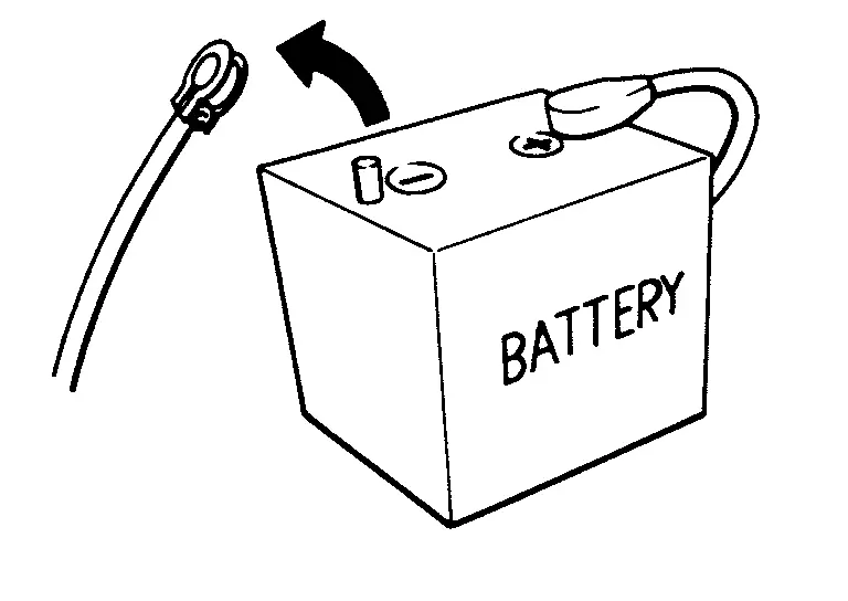
Precautions for Removing Battery Terminal
-
With the adoption of Auto ACC function, ACC power is automatically supplied by operating the Intelligent Key or remote keyless entry or by opening/closing the driver side door. In addition, ACC power is supplied even after the ignition switch is in the OFF position, i.e. ACC power is supplied for a certain fixed time.
-
When disconnecting the 12V battery terminal, place the ignition switch in the OFF position before disconnecting the 12V battery terminal, observing ŌĆ£How to disconnect 12V battery terminalŌĆØ described below.
 NOTE:
NOTE:
Some ECUs operate for a certain fixed time even after ignition switch is in the OFF position and ignition power supply is stopped. If the battery terminal is disconnected before ECU stops, accidental DTC detection or ECU data damage may occur.
-
For Nissan Ariya vehicles with the 2-batteries, be sure to connect the main battery and the sub battery before placing the ignition switch in the ON position.
NOTE:
If the ignition switch is in the ON position with any one of the terminals of main battery and sub battery disconnected, then DTC may be detected.
-
After installing the 12V battery, always check "Self Diagnosis Result" of all ECUs and erase DTC.
NOTE:
The removal of 12V battery may cause a DTC detection error.
HOW TO DISCONNECT 12V BATTERY TERMINAL
Disconnect 12V battery terminal according to instruction described below.
-
Open the hood.
-
Place the ignition switch in the ON position.
-
Place the ignition switch in the OFF position with the driver side door opened.
-
Get out of the Nissan Ariya vehicle and close the driver side door.
-
Wait at least 3 minutes.
CAUTION:
While waiting, never operate the Nissan Ariya vehicle such as locking, opening, and closing doors. Violation of this caution results in the activation of ACC power supply according to the Auto ACC function.
-
Remove 12V battery terminal.
CAUTION:
After installing 12V battery, always check self-diagnosis results of all ECUs and erase DTC.
Preparation
Special Service Tools
|
Tool number (TechMate No.) Tool name | Description | |
|---|---|---|
|
ŌĆö (ŌĆö) Model GR8-1200 Multitasking battery and electrical diagnostic station |
|
Tests batteries, starting and charging systems and charges batteries. For operating instructions, refer to diagnostic station instruction manual. |
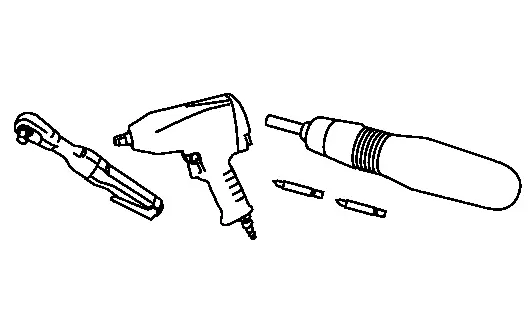
Commercial Service Tools
| Tool name | Description | |
|---|---|---|
| Power tool |
|
Loosening bolts, nuts and screws |
System Description :: Component Parts
Component Parts Location
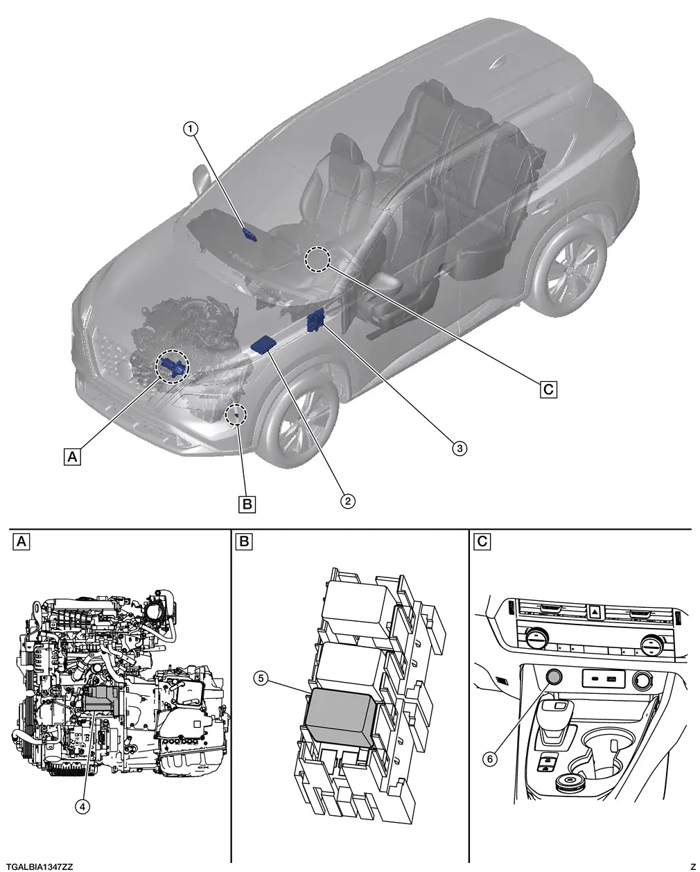
| A. | View with engine and transmission removed | B. | Under left head light | C. | Center console |
| No. | Component | Function |
|---|---|---|
| 1. | Intelligent Key unit | Intelligent Key unit transmits signal to the BCM. Refer to Component Parts Location for detailed component location. |
| 2. | IPDM E/R (Intelligent Power Distribution Module Engine Room) | CPU inside IPDM E/R controls starter relay. Starter relay is built into the IPDM E/R. Refer to System Description. |
| 3. | BCM (Body Control Module | BCM controls the starter cut relay. Refer to System Description. |
| 4. | Starter motor | Refer to Starter motor. |
| 5. | Fuel injector relay and starter cut relay | Power is supplied to the starter cut relay with BCM control. |
| 6. | Push-button ignition switch | Supplies ignition switch status to the Intelligent Key unit. |
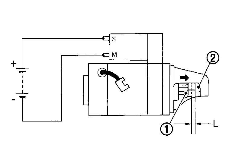
Starter motor
Starter Motor
-
Starter motor is installed on the LH side of the engine.
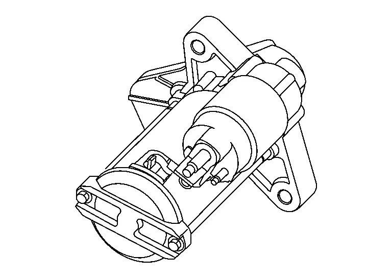
-
The starter motor plunger closes and the motor is supplied with battery power, which in turn cranks the engine, when the "S" terminal is supplied with electric power.
-
"B" terminal: The "B: terminal is constantly supplied with battery power.
-
"S" terminal: The starter motor magnetic switch ("S" terminal) is supplied with power when the cranking condition is satisfied.
System Description :: System
System Description
SYSTEM DIAGRAM
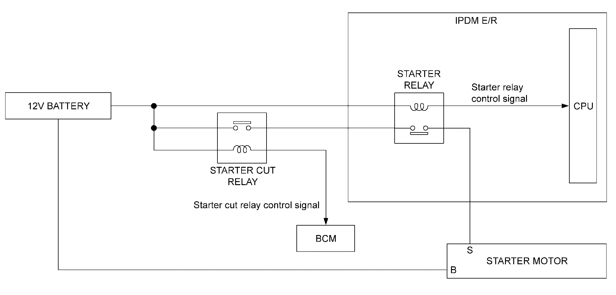
| Component | Function | |
|---|---|---|
| Starter motor | Refer to or Removal and Installation. | |
| IPDM E/R |
CPU inside IPDM E/R controls starter relay. Refer to Component Parts Location. |
|
| BCM |
BCM controls starter cut relay. Refer to Component Parts Location. |
|
| Starter cut relay | Power is supplied to the starter cut relay with BCM control. | |
SYSTEM DESCRIPTION
-
ŌĆ£BŌĆØ terminal is constantly supplied with 12V battery power.
-
When starter operating condition is satisfied, IPDM E/R turns starter relay ON by starter relay control signal.
-
When engine cranking condition is satisfied, BCM turns starter cut relay ON by starter cut relay control signal.
-
Then 12V battery power is supplied to starter motor (ŌĆ£SŌĆØ terminal) through starter cut relay and starter relay.
Wiring Diagram :: Starting System
Wiring Diagram
Refer to Wiring Diagram.
Basic Inspection :: Diagnosis and Repair Work Flow
Work Flow
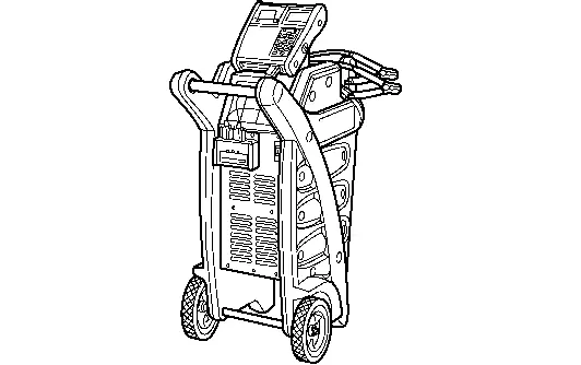
WORK FLOW (WITH 165-DSS-5000P)
STARTING SYSTEM DIAGNOSIS WITH 165-DSS-5000P
To test the starting system, use the following special service tool:
-
Battery and electrical diagnostic analyzer 165-DSS-5000P.
NOTE:
Refer to the diagnostic analyzer instruction manual for proper starting system diagnosis procedures.
Overall Sequence
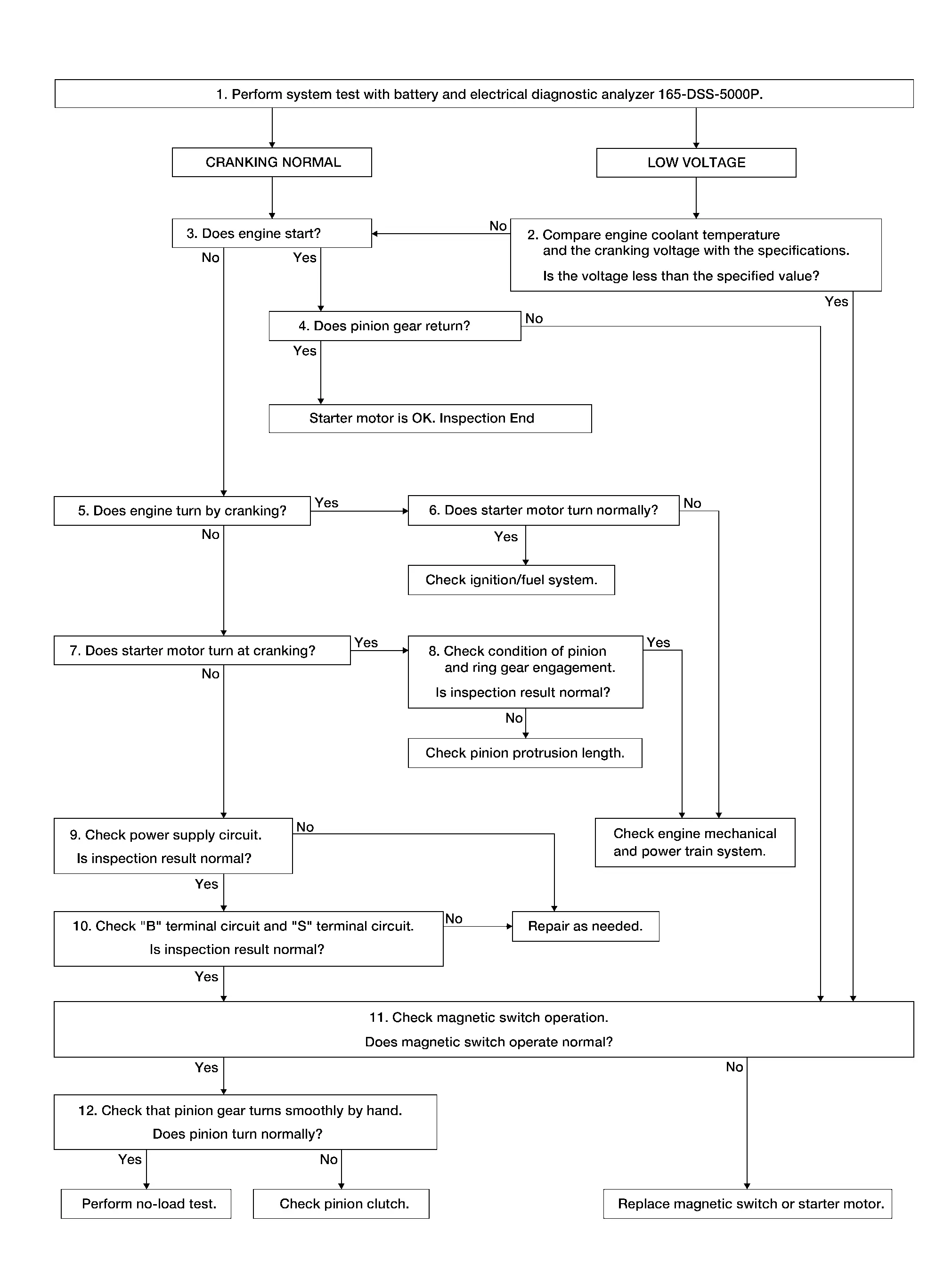
Detailed Flow
NOTE:
-
To ensure a complete and thorough diagnosis, the battery, starter motor and generator test segments must be done as a set from start to finish.
DIAGNOSIS WITH BATTERY AND ELECTRICAL DIAGNOSTIC ANALYZER 165-DSS-5000P
Perform system test with battery and electrical daignostic analyzer 165-DSS-5000P. For details and operating instructions, refer to diagnostic analyzer instruction manual.
How is the test result?
CRANKING NORMAL>>GO TO 3.
LOW VOLTAGE>>GO TO 2.
CHARGE BATTERY>>Perform the slow battery charging procedure. (Initial rate of charge is 10A for 12 hours.) Perform battery test again. Refer to diagnostic analyzer instruction manual.
REPLACE BATTERY>>Before replacing battery, clean the battery cable clamps and battery posts. Perform battery test again. Refer to diagnostic analyzer instruction manual. If second test result is ŌĆ£REPLACE BATTERYŌĆØ, then do so. Perform battery test again to confirm repair.
COMPARISON BETWEEN ENGINE COOLANT AND CRANKING VOLTAGE
Compare engine coolant temperature and the cranking voltage with the specifications.
| Engine coolant temperature [┬░F (┬░C)] | Voltage [V] |
|---|---|
| ŌłÆ22 to ŌłÆ4 (ŌłÆ30 to ŌłÆ20) | 8.6 |
| ŌłÆ2 to 14 (ŌłÆ19 to ŌłÆ10) | 9.1 |
| 16 to 32 (ŌłÆ9 to 0) | 9.5 |
| More than 34 (More than 1) | 9.9 |
Is the voltage less than the specified value?
YES>>GO TO 11.
NO>>GO TO 3.
CHECK ENGINE START
Crank engine and check that engine starts.
Does engine start?
YES>>GO TO 4.
NO>>GO TO 5.
CHECK RETURN OF PINION GEAR
Check that pinion gear returns to original position after engine starts.
Does pinion gear return?
YES>>Starter motor is OK. Inspection End
NO>>GO TO 11.
CHECK ENGINE SPEED WITH CRANKING
Check that engine turns while cranking.
Does engine turn while cranking?
YES>>GO TO 6.
NO>>GO TO 7.
CHECK STARTER MOTOR TURNING WITH CRANKING
Check that starter motor runs smoothly without abnormal noise at cranking.
Does starter motor turn normally?
YES>>Check ignition/fuel system.
NO>>Check engine mechanical and power train system.
CHECK STARTER MOTOR SPEED WITH CRANKING
Check that starter motor turns while cranking.
Does starter motor turn at cranking?
YES>>GO TO 8.
NO>>GO TO 9.
CHECK PINION GEAR AND RING GEAR ENGAGEMENT
Check condition of pinion and ring gear engagement.
Is inspection result normal?
YES>>Check engine mechanical and power train system.
NO>>Check pinion protrusion length. Refer to Inspection.
CHECK POWER SUPPLY CIRCUIT
Check the following conditions.
-
Fuse and fusible link
-
Charge condition, corrosion and connection condition of battery. Refer to Diagnosis Procedure.
Are these inspection results normal?
YES>>GO TO 10.
NO>>Repair as needed.
CHECK STARTING SYSTEM WIRING
Check the following.
-
ŌĆ£BŌĆØ terminal circuit. Refer to Diagnosis Procedure.
-
ŌĆ£SŌĆØ terminal circuit. Refer to Diagnosis Procedure.
Are these inspection results normal?
YES>>GO TO 11.
NO>>Repair as needed.
CHECK MAGNETIC SWITCH OPERATION
Check magnetic switch operation. Refer to Inspection.
Does magnetic switch operate normal?
YES>>GO TO 12.
NO>>Replace magnetic switch or starter motor.
CHECK PINION TURNING
-
Remove starter motor.
-
Check that pinion turns smoothly by hand.
Does pinion turn normally?
YES>>Perform no-load test of starter motor. Refer to Inspection.
NO>>Check pinion clutch. Refer to Inspection.
WORK FLOW (WITHOUT 165-DSS-5000P)
Overall Sequence
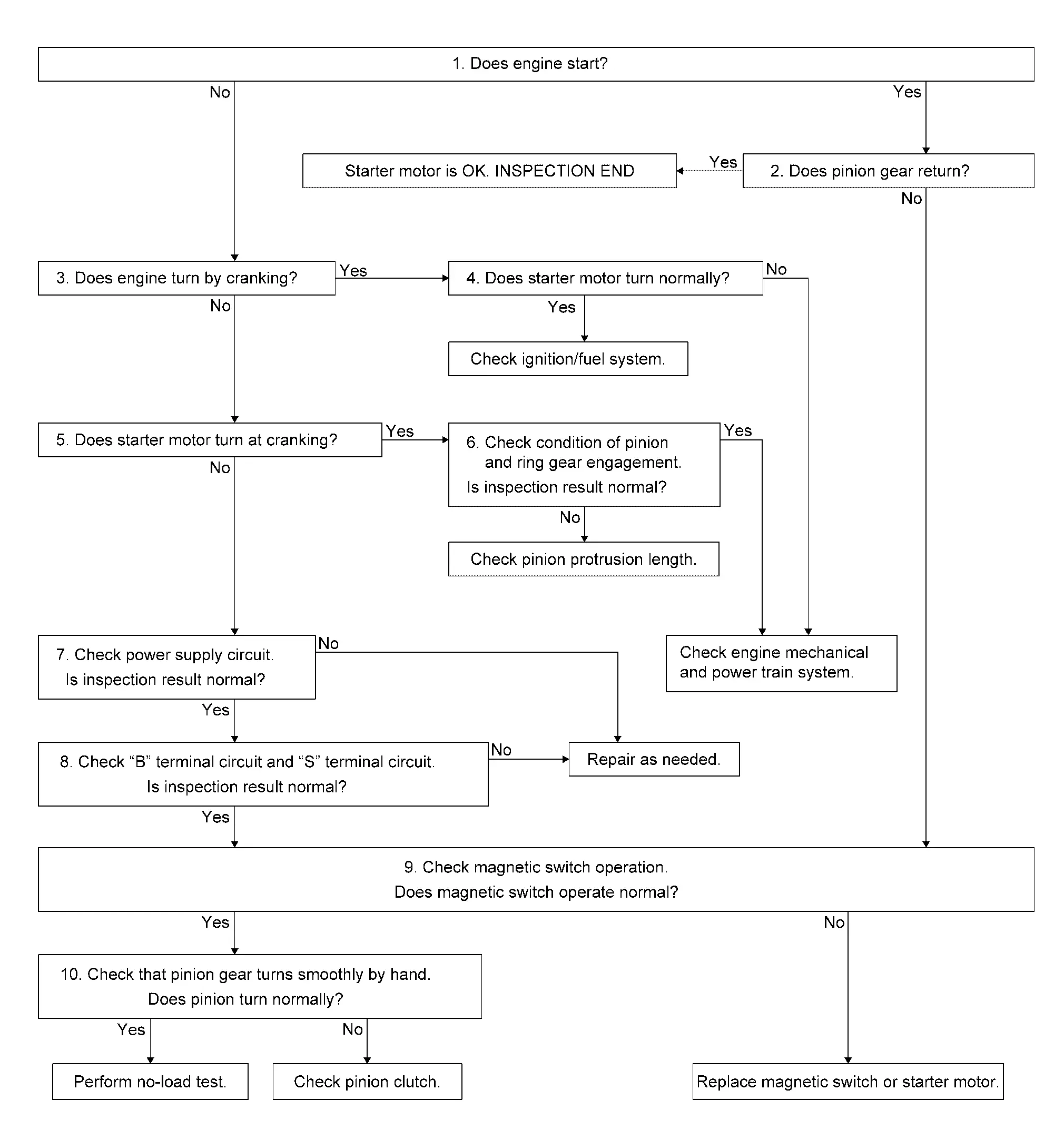
Detailed Flow
NOTE:
If any malfunction is found, immediately disconnect the battery cable from the negative terminal.
CHECK ENGINE START
Crank engine and check that engine starts.
Does engine start?
YES>>GO TO 2.
NO>>GO TO 3.
CHECK RETURN OF PINION GEAR
Check that pinion gear returns to original position after engine starts.
Does pinion gear return?
YES>>Starter motor is OK. Inspection End.
NO>>GO TO 9.
CHECK ENGINE SPEED WITH CRANKING
Check that engine turns while cranking.
Does engine turn by cranking?
YES>>GO TO 4.
NO>>GO TO 5.
CHECK STARTER MOTOR TURNING WITH CRANKING
Check that starter motor runs smoothly without abnormal noise at cranking.
Does starter motor turn normally?
YES>>Check ignition/fuel system.
NO>>Check engine mechanical and power train system.
CHECK STARTER MOTOR SPEED WITH CRANKING
Check that starter motor turns while cranking.
Does starter motor turn at cranking?
YES>>GO TO 6.
NO>>GO TO 7.
CHECK PINION GEAR AND RING GEAR ENGAGEMENT
Check condition of pinion and ring gear engagement.
Is inspection result normal?
YES>>Check engine mechanical and power train system.
NO>>Check pinion protrusion length. Refer to Inspection.
CHECK POWER SUPPLY CIRCUIT
Check the following conditions.
-
Fuse and fusible link
-
Charge condition, corrosion and connection condition of battery. Refer to Diagnosis Procedure.
Are these inspection results normal?
YES>>GO TO 8.
NO>>Repair as needed.
CHECK STARTING SYSTEM WIRING
Check the following.
-
ŌĆ£BŌĆØ terminal circuit. Refer to Diagnosis Procedure.
-
ŌĆ£SŌĆØ terminal circuit. Refer to Diagnosis Procedure.
Are these inspection results normal?
YES>>GO TO 9.
NO>>Repair as needed.
CHECK MAGNETIC SWITCH OPERATION
Check magnetic switch operation. Refer to Inspection.
Does magnetic switch operate normal?
YES>>GO TO 10.
NO>>Replace magnetic switch or starter motor.
CHECK PINION TURNING
-
Remove starter motor.
-
Check that pinion turns smoothly by hand.
Does pinion turn normally?
YES>>Perform no-load test of starter motor. Refer to Inspection.
NO>>Check pinion clutch. Refer to Inspection.
Dtc/circuit Diagnosis :: B Terminal Circuit
Diagnosis Procedure
CAUTION:
Perform diagnosis under the condition that engine cannot start by the following procedure.
-
Remove fuel pump fuse.
-
Crank or start the engine (where possible) until the fuel pressure is released.
CHECK ŌĆ£BŌĆØ TERMINAL CIRCUIT
-
Ignition switch OFF.
-
Check that starter motor ŌĆ£BŌĆØ terminal connection is clean and tight.
-
Check voltage between starter motor ŌĆ£BŌĆØ terminal and ground.
(+) (ŌĆō) Voltage Starter motor Connector Terminal F69 B Ground Battery voltage
Is the inspection result normal?
YES>>GO TO 2.
NO>>Check harness between 12V battery and starter motor for open circuit.
CHECK BATTERY CABLE CONNECTION STATUS (VOLTAGE DROP TEST)
-
Shift selector lever to ŌĆ£PŌĆØ or ŌĆ£NŌĆØ position.
-
Check voltage between 12V battery positive terminal and starter motor ŌĆ£BŌĆØ terminal.
(+) (ŌĆō) Condition Voltage Starter motor Terminal Connector Terminal 12V battery positive terminal F69 B When the ignition switch is in START position Less than 0.5 V
Is the inspection result normal?
YES>>GO TO 3.
NO>>Check harness between 12V battery and starter motor for poor continuity.
CHECK GROUND CIRCUIT STATUS (VOLTAGE DROP TEST)
-
Shift selector lever to ŌĆ£PŌĆØ or ŌĆ£NŌĆØ position.
-
Check voltage between starter motor case and 12V battery negative terminal.
| Terminals | Condition | Voltage | |
|---|---|---|---|
| (+) | (ŌĆō) | ||
| Starter motor case | 12V battery negative terminal | When the ignition switch is in START position | Less than 0.5 V |
Is the inspection result normal?
YES>>ŌĆ£BŌĆØ terminal circuit is OK. Further inspection is necessary. Refer to Work Flow.
NO>>Check starter motor case and ground for poor continuity.
Dtc/circuit Diagnosis :: S Terminal Circuit
Diagnosis Procedure
CAUTION:
Perform diagnosis under the condition that engine cannot start by the following procedure:
-
Remove fuel pump fuse.
-
Crank or start the engine (where possible) until the fuel pressure is released.
CHECK ŌĆ£SŌĆØ TERMINAL CIRCUIT
-
Ignition switch OFF.
-
Disconnect starter motor connector.
-
Shift selector lever to ŌĆ£PŌĆØ or ŌĆ£NŌĆØ position.
-
Check voltage between starter motor harness connector and ground.
(+) (ŌĆō) Condition Voltage Starter motor Connector Terminal F53 S Ground When the ignition switch is in START position Battery voltage
Is the inspection result normal?
YES>>ŌĆ£SŌĆØ terminal circuit is OK. Further inspection is necessary. Refer to Work Flow.
NO>>GO TO 2.
CHECK HARNESS CONTINUITY (OPEN CIRCUIT)
-
Ignition switch OFF.
-
Disconnect IPDM E/R harness connector.
-
Check continuity between starter motor harness connector and IPDM E/R harness connector.
Starter motor IPDM E/R Continuity Connector Terminal Connector Terminal F53 S F41 83 Yes -
Check continuity between IPDM E/R harness connector and ground.
IPDM E/R ŌĆö Continuity Connector Terminal F41 83 Ground No
Is the inspection result normal?
YES>>Further inspection is necessary. Refer to Work Flow.
NO>>Repair harness.
Symptom Diagnosis :: Starting System
Symptom Table
| Symptom | Reference |
|---|---|
| No normal cranking | Refer to Work Flow. |
| Starter motor does not rotate |
Removal and Installation :: Starter Motor. Kr15ddt
Kr15ddt
Exploded View
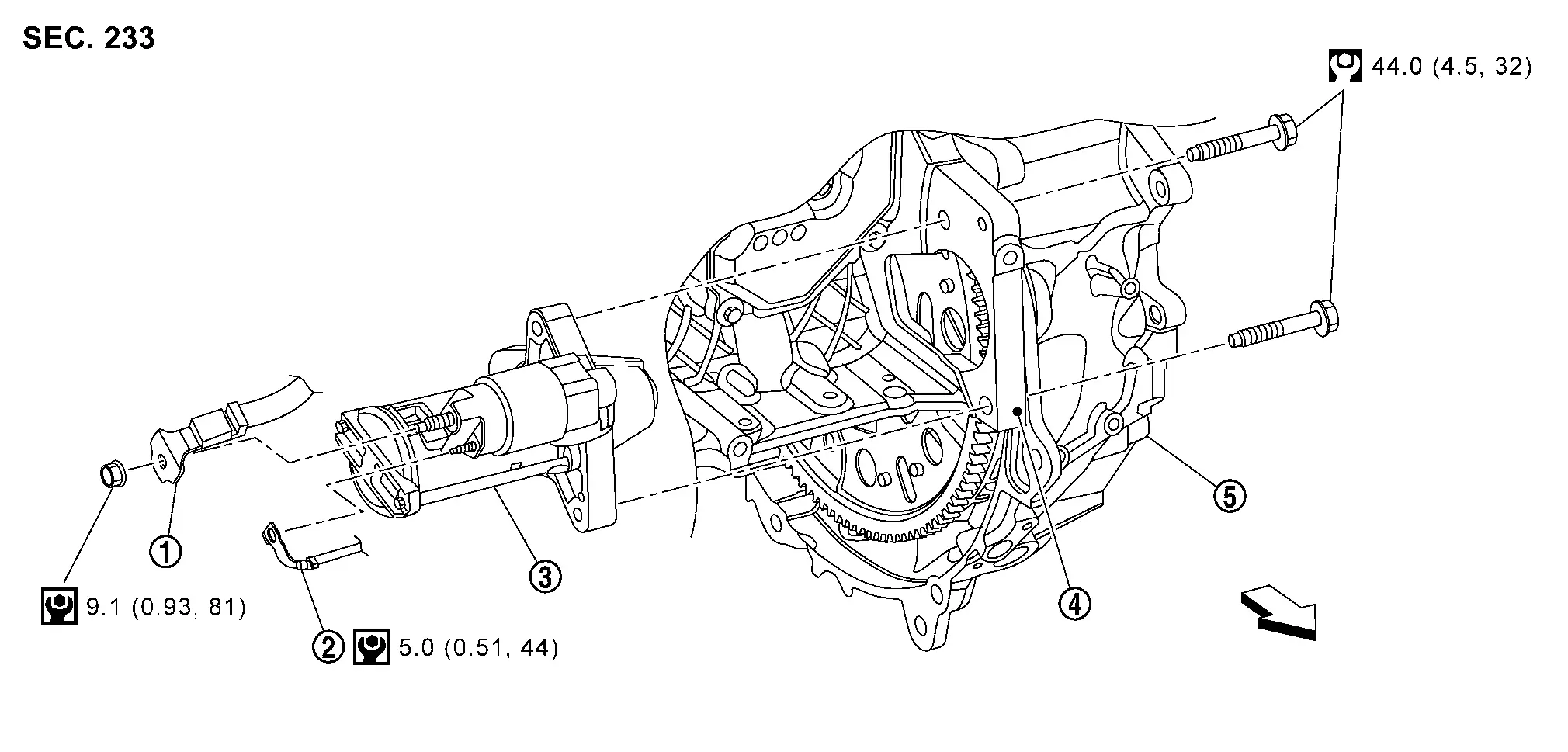
 |
ŌĆ£BŌĆØ terminal harness |  |
ŌĆ£SŌĆØ terminal harness (with ŌĆ£SŌĆØ terminal nut) |  |
Starter motor |
 |
Engine block |  |
Transaxle assembly | ||
| : Nissan Ariya Vehicle front | |||||
 |
: N┬Ęm (kg-m, in-lb) | ||||
 |
: N┬Ęm (kg-m, ft-lb) | ||||
Removal and Installation
REMOVAL
Disconnect battery cable from negative terminal. Refer toPrecautions for Removing Battery Terminal.
Remove air cleaner assembly. Refer to Removal and Installation.
Remove starter motor upper side mounting bolt.
Remove engine under cover. Refer to Removal and Installation.
Disconnect VCR actuator harness connectors (A) and (B), and then disengage harness fixing clip.
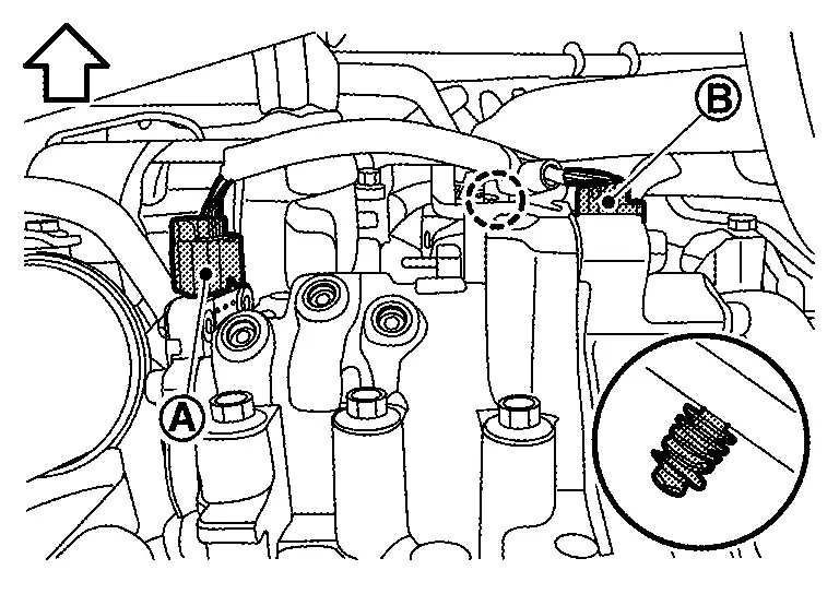
 |
: Clip |
| : Nissan Ariya Vehicle front |
Disconnect VCR actuator harness connector (A), and then remove harness bracket mounting bolt (B).
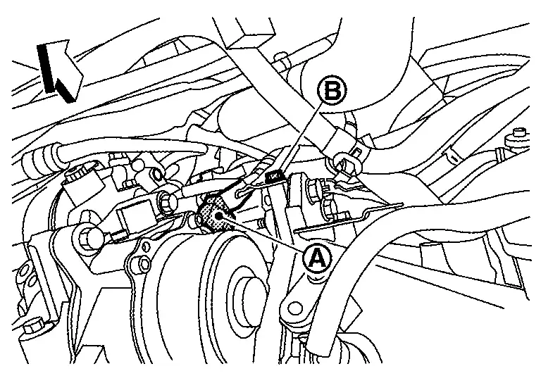
| : Nissan Ariya Vehicle front |
Disconnect crank angle sensor harness connector (A) and disengage harness fixing clip.
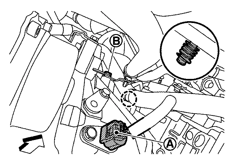
|
: Clip |
| : Nissan Ariya Vehicle front |
Remove harness bracket mounting bolt (B).
Loosen "S" terminal harness nut, and then disconnect "S" terminal harness (with "S" terminal harness nut).
Remove front tire assembly RH. Refer to Removal & Installation.
Remove splash guard RH. Refer to Removal and Installation.
Remove drive belt. Refer to Removal and Installation.
Remove "B" terminal harness mounting nut, and then disconnect "B" terminal harness.
Remove starter motor lower side mounting bolt, and then remove starter motor downward from Nissan Ariya vehicle.
INSTALLATION
Note the following items, and then install in the reverse order of removal.
CAUTION:
-
Install ŌĆ£BŌĆØ terminal harness (1) and ŌĆ£SŌĆØ terminal harness (2) to starter motor in following installation angle.
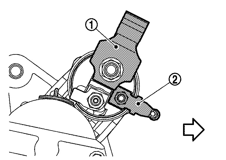

: Nissan Ariya Vehicle front -
Be careful to tighten ŌĆ£BŌĆØ terminal nut to the specified torque. Refer to Exploded View.
Inspection
MAGNETIC SWITCH
Remove starter motor from vehicle. Refer to Removal and Installation.
Connect 12V battery to starter motor as shown in the figure. Check that pinion gear (1) is driven out by magnetic switch.
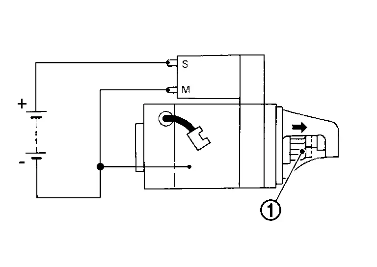
-
Replace starter motor if pinion gear is not driven out.
Disconnect ŌĆ£MŌĆØ terminal as shown in the figure. Check that pinion gear (1) does not return to original position.
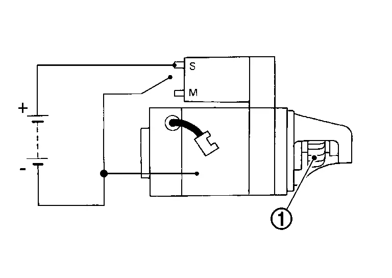
-
Replace starter motor if pinion gear returns.
Disconnect (-) wire from starter motor body as shown in the figure. Check that pinion gear (1) returns to original position.
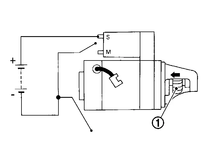
-
Replace starter motor if pinion gear does not return.
PINION PROTRUSION LENGTH
With pinion gear (1) driven out by magnetic switch, push pinion gear back to remove slack and measure the clearance ŌĆ£LŌĆØ between the front edge of the pinion gear and the pinion stopper (2).
| Clearance ŌĆ£LŌĆØ | : Refer to Starter Motor. |
-
Replace starter motor if the measurement value is not within specifications.
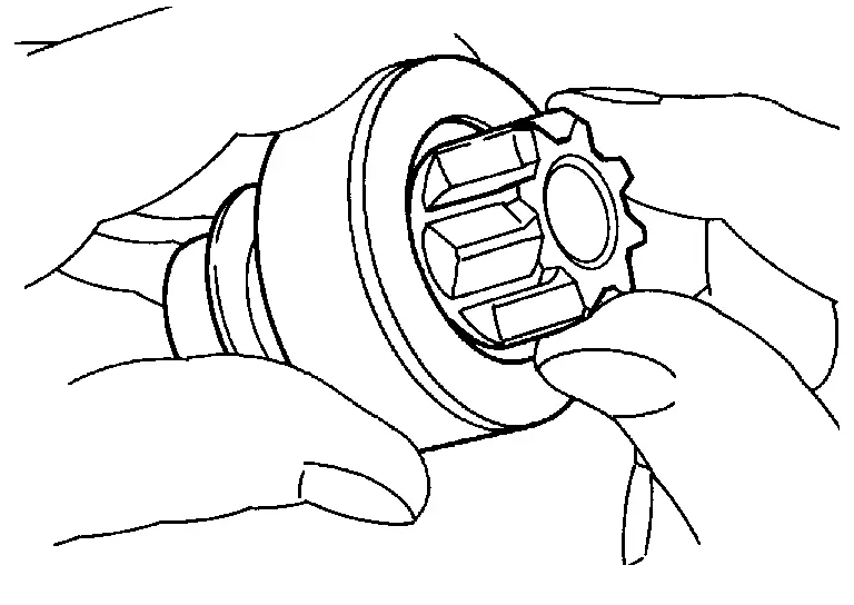
PINION CLUTCH
Check pinion gear teeth.
-
Replace starter motor if teeth are worn or damaged. (Also check condition of ring gear teeth.)
Check to see if pinion locks in one direction and rotates smoothly in the opposite direction.
-
Replace starter motor if pinion is locked, rotates in both directions or unusual resistance is evident.
NO-LOAD TEST
Remove starter motor from vehicle. Refer to Removal and Installation.
Connect 12V battery and ammeter to starter motor as shown in the figure. Check no load current with pinion gear (1) driven out and starter motor operating.
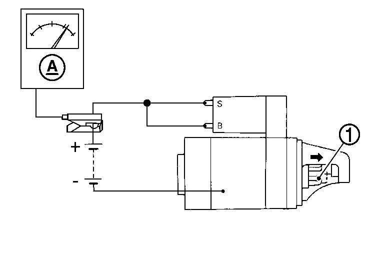
| No-load current | : Refer to Starter Motor. |
-
Replace starter motor if the measurement value is not within specifications
Service Data and Specifications (sds)
Starter Motor
| Engine | KR15DDT | ||
| Type | 143N | ||
| SEG Automotive make | |||
| Reduction gear type | |||
| System voltage | [V] | 12 | |
| No-load | Terminal voltage | [V] | 11.6 |
| Current | [A] | Less than 55 | |
| Revolution | [rpm] | More than 3,887 | |
| Clearance "L" between pinion front edge and pinion stopper | [mm (in)] |
13.2 (0.520) |
|
| Engine | KR15DDT | ||
| Type | MOOOTB0671ZC | ||
| Mitsubushi make | |||
| Reduction gear type | |||
| System voltage | [V] | 12 | |
| No-load | Terminal voltage | [V] | 11 |
| Current | [A] | Less than 90 | |
| Revolution | [rpm] | More than 2,400 | |
| Clearance "L" between pinion front edge and pinion stopper | [mm (in)] |
13.2 (0.520) |
|
Other materials:
Rear Final Drive: R145. Periodic Maintenance. Rear Differential Gear Oil
Rear Differential Gear Oil
Inspection
OIL LEAKAGEMake sure that oil is not leaking from final drive assembly or around it.OIL LEVELCheck
oil level from filler plug mounting hole as shown in the figure after
removing filler plug (1) and gasket from final drive assembly.
: Nissan Ariya Veh ...
Front Drive Shaft (kr15ddt)
Exploded View
LEFT SIDE 1.
Circular clip
2.
Dust shield
3.
Housing
4.
Snap ring
5.
Spider assembly
6.
Stopper ring
7.
Boot band
8.
Boot
9.
Shaft
10.
Damper band
11.
Dynamic damper
12.
Circular clip
13.
Joint sub-asse ...
Symptom Diagnosis. Reminder Function Does Not Operate
Door Request Switch
Description
Reminder function does not operate using door request switch.
Diagnosis Procedure
CHECK ŌĆ£ANSWER BACKŌĆØ SETTING IN ŌĆ£WORK SUPPORTSŌĆØ
CONSULT
Select ŌĆ£Answer backŌĆØ in ŌĆ£Work supportsŌĆØ mode of "INTELLIGENT KEY".
Check the ŌĆ£Answer backŌĆØ in Ō ...