Nissan Rogue (T33) 2021-Present Service Manual: Engine :: Exhaust System
Kr15ddt :: Precaution. Precautions
Precautions
Precaution for Supplemental Restraint System (SRS) "AIR BAG" and "SEAT BELT PRE-TENSIONER"
The Supplemental Restraint System such as “AIR BAG” and “SEAT BELT PRE-TENSIONER”, used along with a front seat belt, helps to reduce the risk or severity of injury to the driver and front passenger for certain types of collisions.
Information necessary to service the system safely is included in the “SRS AIR BAG” and “SEAT BELT” sections of this Service Manual.
WARNING:
Always observe the following items for preventing accidental activation:
-
To avoid rendering the SRS inoperative, which could increase the risk of personal injury or death in the event of a collision that would result in air bag inflation, it is recommended that all maintenance and repair be performed by an authorized NISSAN/INFINITI dealer.
-
Improper repair, including incorrect removal and installation of the SRS, can lead to personal injury caused by unintentional activation of the system. For removal of Spiral Cable and Air Bag Module, see “SRS AIR BAG”.
-
Never use electrical test equipment on any circuit related to the SRS unless instructed to in this Service Manual. SRS wiring harnesses can be identified by yellow and/or orange harnesses or harness connectors.
PRECAUTIONS WHEN USING POWER TOOLS (AIR OR ELECTRIC) AND HAMMERS
WARNING:
Always observe the following items for preventing accidental activation:
-
When working near the Air Bag Diagnosis Sensor Unit or other Air Bag System sensors with the ignition/power switch ON or engine running, never use air or electric power tools or strike near the sensor(s) with a hammer. Heavy vibration could activate the sensor(s) and deploy the air bag(s), possibly causing serious injury.
-
When using air or electric power tools or hammers, always switch the ignition/power switch OFF, disconnect the 12V battery or batteries, and wait at least 3 minutes before performing any service.
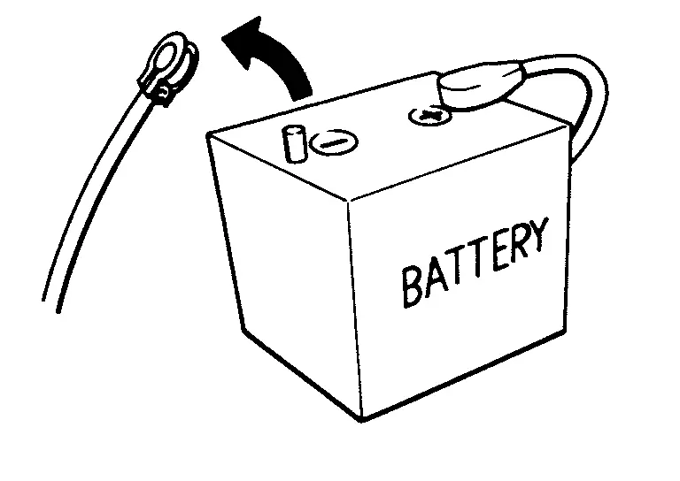
Precautions for Removing Battery Terminal
-
With the adoption of Auto ACC function, ACC power is automatically supplied by operating the Intelligent Key or remote keyless entry or by opening/closing the driver side door. In addition, ACC power is supplied even after the ignition switch is in the OFF position, i.e. ACC power is supplied for a certain fixed time.
-
When disconnecting the 12V battery terminal, place the ignition switch in the OFF position before disconnecting the 12V battery terminal, observing “How to disconnect 12V battery terminal” described below.
 NOTE:
NOTE:
Some ECUs operate for a certain fixed time even after ignition switch is in the OFF position and ignition power supply is stopped. If the battery terminal is disconnected before ECU stops, accidental DTC detection or ECU data damage may occur.
-
For Nissan Ariya vehicles with the 2-batteries, be sure to connect the main battery and the sub battery before placing the ignition switch in the ON position.
NOTE:
If the ignition switch is in the ON position with any one of the terminals of main battery and sub battery disconnected, then DTC may be detected.
-
After installing the 12V battery, always check "Self Diagnosis Result" of all ECUs and erase DTC.
NOTE:
The removal of 12V battery may cause a DTC detection error.
HOW TO DISCONNECT 12V BATTERY TERMINAL
Disconnect 12V battery terminal according to instruction described below.
-
Open the hood.
-
Place the ignition switch in the ON position.
-
Place the ignition switch in the OFF position with the driver side door opened.
-
Get out of the Nissan Ariya vehicle and close the driver side door.
-
Wait at least 3 minutes.
CAUTION:
While waiting, never operate the Nissan Ariya vehicle such as locking, opening, and closing doors. Violation of this caution results in the activation of ACC power supply according to the Auto ACC function.
-
Remove 12V battery terminal.
CAUTION:
After installing 12V battery, always check self-diagnosis results of all ECUs and erase DTC.
Removal and Installation
CAUTION:
-
Be sure to use genuine exhaust system parts or equivalents which are specially designed for heat resistance, corrosion resistance, and shape.
-
Perform the operation with the exhaust system fully cooled down because the system will be hot just after engine stops.
-
Be careful not to cut your hand on the heat insulator edge.
-
Never use silicon-containing products (e.g. oil) to prevent malfunctions such as the interference with the conduction of electricity and the occurrence of noise in the radio.
-
Prevent rust preventives from adhering to the sensor body.
Kr15ddt :: Preparation. Preparation
Preparation
Commercial Service Tools
| Tool name | Description | |
|---|---|---|
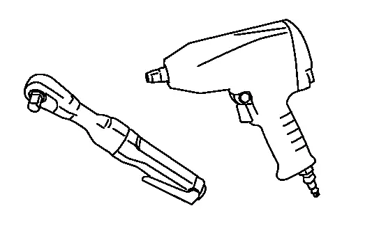
| Power tool |
|
Loosening nuts and bolts |
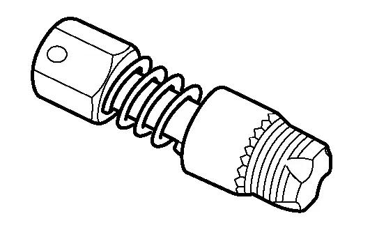
| Oxygen sensor thread cleaner |
|
Reconditioning the exhaust system threads before installing a new oxygen sensor (Use with anti-seize lubricant shown below.)
|
Kr15ddt :: Periodic Maintenance. Exhaust System
Exhaust System
Inspection
Check exhaust pipes, muffler, and mounting for improper attachment, leakage, cracks, damage or deterioration.
-
If anything is found, repair or replace damaged parts.
Kr15ddt :: Removal and Installation. Exhaust System
Exhaust System
Exploded View
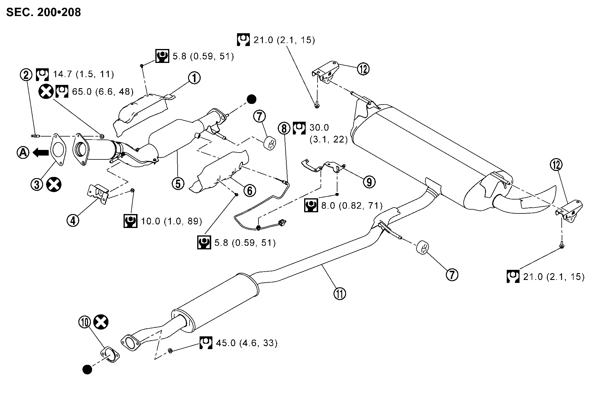
 |
Heat insulator (upper) |  |
Stud bolt |  |
Gasket |
 |
Mounting rubber |  |
Exhaust front tube |  |
Heat insulator (lower) |
 |
Mounting rubber |  |
Exhaust gas temperature sensor |  |
Bracket |
 |
Gasket |  |
Main muffler |  |
Mounting rubber |
 |
: To three way catalyst. Refer to Exploded View. | ||||
 |
: Always replace after every disassembly. | ||||
 |
: N·m (kg-m, in-lb) | ||||
 |
: N·m (kg-m, ft-lb) | ||||
  : Indicates that the part is connected at points with same symbol in actual Nissan Ariya vehicle.  : Indicates that the part is connected at points with same symbol in actual Nissan Ariya vehicle. |
|||||
Removal and Installation
REMOVAL
-
Disconnect each joint and mounting.
-
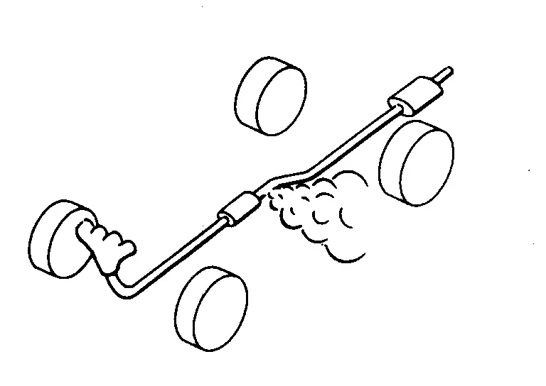
Remove exhaust gas temperature sensor with following procedure.
-
Disconnect exhaust gas temperature sensor harness connector.
-
Remove exhaust gas temperature sensor harness bracket.
-
Disconnect exhaust gas temperature sensor harness from heat insulator (lower).
-
Using crowfoot (A), removal exhaust gas temperature sensor
.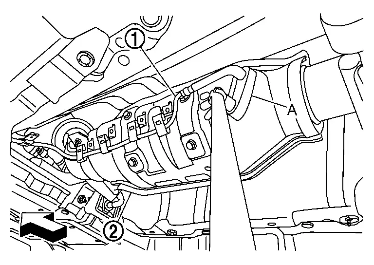
: Exhaust front tube 
: Nissan Ariya Vehicle front CAUTION:
Discard any sensor which has been dropped from a height of more than 0.5 m (19.7 in) onto a hard surface such as a concrete floor; use a new one.
-
INSTALLATION
Note the following, and install in the reverse order of removal.
CAUTION:
-
Always replace gaskets with new ones when reassembling.
-
If heat insulator is badly deformed, repair or replace it. If deposits such as mud pile up on the heat insulator, remove them.
-
Before installing a new exhaust gas temperature sensor, clean exhaust system threads using the oxygen sensor thread cleaner and apply anti-seize lubricant (commercial service tool).
-
Never over torque exhaust gas temperature sensor. Doing so may cause damage to the exhaust gas temperature sensor, resulting in the “MIL” coming on.
-
When installing heat insulator avoid large gaps or interference between heat insulator and each exhaust pipe.
-
Remove deposits from the sealing surface of each connection. Connect them securely to avoid gas leakage.
-
Temporarily tighten mounting nuts and bolts. Check each part for unusual interference and mounting rubber interference, and then tighten them to the specified torque.
-
When installing each mounting rubber, avoid twisting or unusual extension in up/down, front/rear and right/left directions.
-
Install the mounting rubber with the FR arrow mark facing the front of the vehicle.
Inspection
INSPECTION AFTER INSTALLATION
-
Check clearance between tail tube and rear bumper is even.
-
With engine running, check exhaust tube joints for gas leakage and unusual noises.
-
Check to ensure that mounting brackets and mounting rubbers are installed properly and free from undue stress. Improper installation could result in excessive noise and vibration.
Other materials:
Rear View Monitor. Precaution. Precautions
Precautions
Precaution for Supplemental Restraint System (SRS) "AIR BAG" and "SEAT BELT PRE-TENSIONER"
The Supplemental Restraint System such as “AIR BAG” and “SEAT BELT
PRE-TENSIONER”, used along with a front seat belt, helps to reduce the
risk or severity of injury to the driver and ...
Air Pressure Monitor
CONSULT Function [BCM - AIR PRESSURE MONITOR]
DATA MONITORNOTE:
The following table includes information [items]
inapplicable to this Nissan Ariya vehicle. For information [items]
applicable to this vehicle, refer to CONSULT display items.
Monitor Item
[Unit] Description
Tire status-r ...
Kr15ddt. Service Data and Specifications (sds). Service Data and Specifications (sds)
Service Data and Specifications (sds)
General Specification
GENERAL SPECIFICATIONS Engine type
KR15DDT
Cylinder arrangement
In-line 3
Displacement cm3 (cu in)
Low compression
1,497 (91.40)
High compression
1,477 (90.10)
Bore and stroke mm (in)
Low compression ...