Nissan Rogue (T33) 2021-Present Owner’s Manual & User Guide: Emergency Call (SOS) button
Emergency support
Basic information
NissanConnect Services provide a range of emergency assistance features designed to support the driver of the Nissan Rogue in critical situations.
For example, in the event of a medical emergency or serious injury, pressing the in-vehicle Emergency Call (SOS) button connects you to the NissanConnect Services Response Center. Using GPS, the system can determine your vehicle’s location and, when appropriate, notify police, fire services, or other emergency agencies.
For additional information about NissanConnect Services emergency support, contact the NissanConnect Customer Support line at 1-855-426-6628 or visit the NissanConnect Services website: www.nissanusa.com/connect (U.S.) or www.nissan.ca/nissanconnect (English/French for Canada).
For models with ProPILOT Assist:
Depending on model and configuration, when the Nissan Rogue performs an emergency stop, the system connects you automatically to an Emergency Call operator, who can then dispatch assistance through public emergency services.
WARNING
- The Automatic Collision Notification and Emergency Call functions do NOT operate under the following conditions:
- If the vehicle is not subscribed to NissanConnect Services.
- If the NissanConnect Services network is unavailable.
- If the vehicle leaves the supported geographic service area for the TCU (Telematics Control Unit).
- If cellular network service is unavailable.
- If the vehicle is in an area with poor reception (tunnels, underground parking, behind buildings, mountainous terrain).
- If the line is busy.
- If the TCU or vehicle systems are malfunctioning.
- If damage from a collision prevents the system from operating.
- Park the vehicle safely and apply the parking brake before using the Emergency Call (SOS) button.
- Use this service only in true emergencies. Improper use may result in penalties.
- Radio waves may affect electronic medical devices. Individuals with pacemakers should consult their device manufacturer regarding possible interference before use.
- The TCU antenna is located inside the upper center of the instrument panel. Occupants with medical implants should avoid being closer than the distance recommended by the device manufacturer.
Making an emergency call
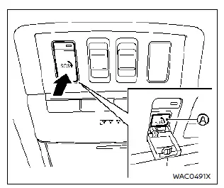
The Emergency Call (SOS) button is positioned near the map light in the Nissan Rogue.
1. Press the cover to reveal the Emergency Call (SOS) button.
2. Press the Emergency Call (SOS) button to initiate the emergency call.
3. Once connected, speak directly with the Response Specialist.
If you need to cancel the emergency call, press and hold the SOS button for several seconds.
NOTE:
- After pressing the SOS button, connection may take several moments depending on network conditions or if the TCU is being used for other services.
- The indicator light on the SOS button shows system readiness. If it is not illuminated, pressing SOS will not connect you to the Response Specialist.
The indicator blinks while connected to the NissanConnect Services Response Center.
- Even if the indicator light is illuminated, connection may still fail. In such cases during an emergency, contact authorities by other available means.
- To avoid accidental disconnection, keep the engine running during the call if conditions allow.
Other materials:
Removal and Installation. Brake Booster
Exploded View
Brake booster
Joint pipe
Vacuum sensor
Gasket
: N·m (kg-m, ft-lb)
: Always replace after every disassembly.
Removal and installation
REMOVALCAUTION:
Never spill or splash brake ...
Precautions on seat belt usage
Wearing your seat belt correctly — sitting upright, positioned well back in the seat, and keeping both feet on the floor — significantly reduces the risk of injury or death in an accident. When used properly, seat belts work together with your Nissan Rogue’s safety systems, including suppleme ...
P212b Admission Valve Position Sensor
DTC Description
DTC DETECTION LOGIC DTC
CONSULT screen terms
(Trouble diagnosis content)
DTC detection condition
P212B
00
Throttle position sensor/switch
(Throttle Position Sensor/Switch "G" Circuit Range/Performance)
Diagnosis condition
IGN ON
Signal (terminal)
A ...