Nissan Rogue (T33) 2021-Present Service Manual: Electric Shift Control Module
Reference Value
CONSULT DATA MONITOR STANDARD VALUE
 NOTE:
NOTE:
The following table includes information (items) inapplicable to this Nissan Ariya vehicle. For information (items) applicable to this vehicle, refer to CONSULT display items.
| Monitor item | Condition | Value/Status (Approx.) | |
|---|---|---|---|
| Range position | Shift position: P position | P | |
| Shift position: R position | R | ||
| Shift position: N position | N | ||
| Shift position: D position | D | ||
| Shift position judgment | Selector lever: H position | H | |
| Selector lever: R position | R | ||
| Selector lever: D/M position | D | ||
| Selector lever: Nr position | Nr | ||
| Selector lever: Nd position | Nd | ||
| Target shift position | Shift position: P position | P | |
| Shift position: N position | R | ||
| Shift position: R position | N | ||
| Shift position: D position | D | ||
| Actual shift position | CVT position: P position | P | |
| CVT position: N position | R | ||
| CVT position: R position | N | ||
| CVT position: D position | D | ||
| Nissan Ariya Vehicle state | Ignition switch is ON (Engine is stopped) | State3 | |
| While engine starting | State4 | ||
| Engine started | State5 | ||
| Shift sensor 1 | Selector lever is held in H (Home), R, and Nr positions | On | |
| Other than the above | Off | ||
| Shift sensor 2 | Selector lever is held in H (Home), R, and Nr positions | On | |
| Other than the above | Off | ||
| Shift sensor 3 | Selector lever is held in H (Home) and Nr positions | On | |
| Other than the above | Off | ||
| Shift sensor 4 | Selector lever is held in H (Home), Nr, and Nd positions | On | |
| Other than the above | Off | ||
| Shift sensor 5 | Selector lever is held in H (Home), Nr, and Nd position | On | |
| Other than the above | Off | ||
| Shift sensor 6 | Selector lever is held in H (Home) and Nd positions | On | |
| Other than the above | Off | ||
| Shift sensor 7 | Selector lever is held in H (Home), D/M, and Nd positions | On | |
| Other than the above | Off | ||
| Shift sensor 8 | Selector lever is held in H (Home), D/M, and Nd positions | On | |
| Other than the above | Off | ||
| P position switch 1 | P position switch is pressed | On | |
| Other than the above | Off | ||
| P position switch 2 | P position switch is pressed | Off | |
| Other than the above | On | ||
| Power supply relay A | Ignition switch is ON | On | |
| Power supply relay B | Ignition switch is ON | Off | |
| Ignition switch | Ignition switch is ON | On | |
| Power supply voltage | Battery voltage: Less than 8.97 V | Low | |
| Battery voltage: 8.97 V or more to 10.8 V or less | Low/ Normal | ||
| Battery voltage: More than 10.8 V | Normal | ||
| ECU power 1 | 10 V or more | High level | |
| 7 V or less | Lower level | ||
| Main power voltage | Ignition switch is ON | 9 ŌĆō 16 V | |
| ECU power 2 | 10 V or more | High level | |
| 7 V or less | Lower level | ||
| Motor A U voltage | No shifting | 9 ŌĆō 16 V | |
| Motor A V voltage | No shifting | 9 ŌĆō 16 V | |
| Motor A W voltage | No shifting | 9 ŌĆō 16 V | |
| Motor B U voltage | No shifting | 9 ŌĆō 16 V | |
| Motor B V voltage | No shifting | 9 ŌĆō 16 V | |
| Motor B W voltage | No shifting | 9 ŌĆō 16 V | |
| Shift sensor 1 voltage | Selector lever is held in H (Home), R, and Nr positions | 1.08 - 2.12 V | |
| Other than the above | 2.68 - 3.28 V | ||
| Shift sensor 2 voltage | Selector lever is held in H (Home), R, and Nr positions | 1.08 - 2.12 V | |
| Other than the above | 2.68 - 3.28 V | ||
| Shift sensor 3 voltage | Selector lever is held in H (Home) and Nr positions | 1.08 - 2.12 V | |
| Other than the above | 2.68 - 3.28 V | ||
| Shift sensor 4 voltage | Selector lever is held in H (Home), Nr, and Nd positions | 1.08 - 2.12 V | |
| Other than the above | 2.68 - 3.28 V | ||
| Shift sensor 5 voltage | Selector lever is held in H (Home), Nr, and Nd positions | 1.08 - 2.12 V | |
| Other than the above | 2.68 - 3.28 V | ||
| Shift sensor 6 voltage | Selector lever is held in H (Home) and Nd positions | 1.08 - 2.12 V | |
| Other than the above | 2.68 - 3.28 V | ||
| Shift sensor 7 voltage | Selector lever is held in H (Home), D/M, and Nd positions | 1.08 - 2.12 V | |
| Other than the above | 2.68 - 3.28 VV | ||
| Shift sensor 8 voltage | Selector lever is held in H (Home), D/M, and Nd positions | 1.08 - 2.12 V | |
| Other than the above | 2.68 - 3.28 V | ||
| P position switch 1 voltage | P position switch is pressed | 1.08 - 2.12 V | |
| Other than the above | 2.68 - 3.28 V | ||
| P position switch 2 voltage | P position switch is pressed | 2.68 - 3.28 V | |
| Other than the above | 1.08 - 2.12 V | ||
TERMINAL LAYOUT
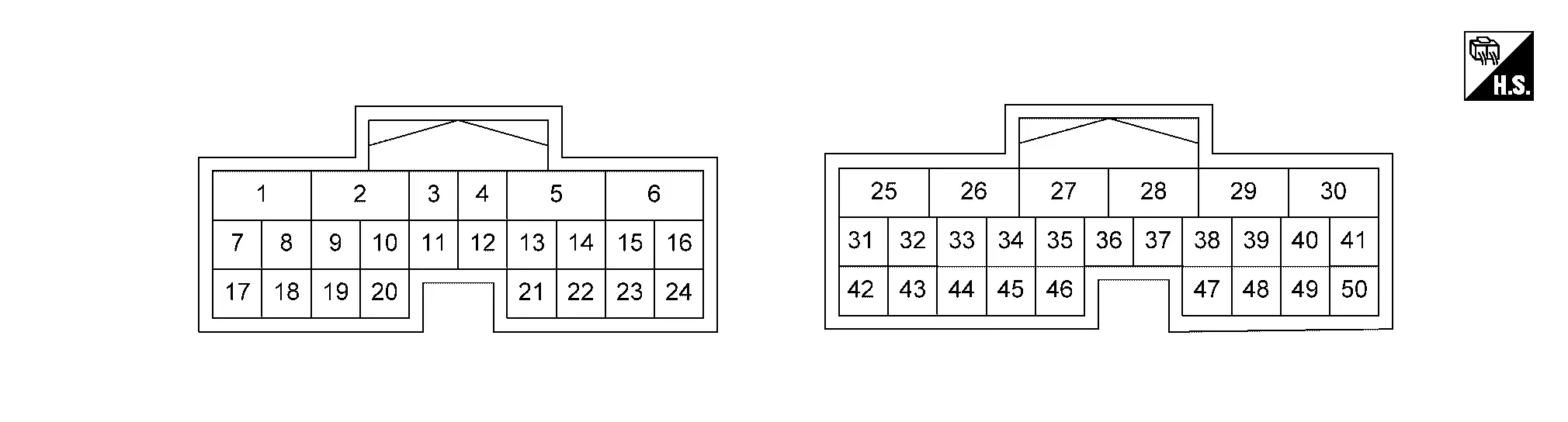
INPUT/OUTPUT SIGNAL STANDARD
|
Terminal No. (Wire color) | Description | Condition | Value (Approx.) | |||
|---|---|---|---|---|---|---|
| + | ŌłÆ | Signal | Input/Output | |||
|
1 (R) |
Ground | Motor phase U | Output | Engine: Running | No shifting |
|
| When shift position is changed |
|
|||||
|
2 (Y) |
Ground | Motor phase V | Output | Engine: Running | No shifting |
|
| When shift position is changed |
|
|||||
|
3 (B) |
Ground | Signal ground 1 | ŌĆö | Always | 0 V | |
|
4 (B) |
Ground | Signal ground 2 | ŌĆö | Always | 0 V | |
|
5 (BR) |
Ground | Motor phase W | Output | Engine: Running | No shifting |
|
| When shift position is changed |
|
|||||
|
6 (B) |
Ground | Power ground 1 | ŌĆö | Always | 0 V | |
|
7 (BG) |
Ground | M position output | Output | Engine: Running | Driving with manual mode | 0 V |
| Other than the above | 11.3 V | |||||
|
8 (W) |
Ground | Power supply 1 | Input | Always | 9 ŌĆō 16 V | |
|
9 (BR) |
Ground | Ignition switch 1 | Input | Ignition switch: ON | 9 ŌĆō 16 V | |
| Ignition switch: OFF | 0 V | |||||
|
15 (P) |
Ground | Encoder sensor B | Input | Engine: Running | No shifting |
or
|
| When shift position is changed |
|
|||||
|
16 (R)*┬╣ (SB)*┬▓ |
Ground | Encoder sensor power supply | Output | Ignition switch: ON | 5 V | |
|
18 (SB) |
Ground | Shift actuator relay control | Output | Ignition switch: ON | 0.7 V | |
| Ignition switch: OFF | 9 ŌĆō 16 V | |||||
|
19 (V) |
Ground | Electric shift sensor power supply 1 | Output | Ignition switch: ON | 5 V | |
|
22 (L) |
Ground | N position output | Output | Engine: Running | CVT position: N position | 0 V |
| Other than the above | 11.3 V | |||||
|
23 (G) |
Ground | Encoder sensor ground | ŌĆö | Always | 0 V | |
|
24 (BR) |
Ground | Encoder sensor A | Input | Engine: Running | No shifting |
or
|
| When shift position is changed |
|
|||||
|
25 (B) |
Ground | Power ground 2 | ŌĆö | Always | 0 V | |
|
26 (R)*┬╣ (B)*┬▓ |
Ground | D position output | Output | Engine: Running | CVT position: D position | 0 V |
| Other than the above | 11.3 V | |||||
|
30 (W) |
Ground | R position output | Output | Engine: Running | CVT position: R position | 0 V |
| Other than the above | 11.3 V | |||||
|
31 (GR) |
Ground | CAN-H | Input/Output | ŌĆö | ŌĆö | |
|
32 (R) |
Ground | CAN-L | Input/Output | ŌĆö | ŌĆö | |
|
34 (Y) |
Ground | Electric shift sensor 1 | Input | Ignition switch: ON | Selector lever is held in H (Home), R, and Nr positions | 1.08 - 2.12 V |
| Other than the above | 2.68 - 3.28 V | |||||
|
35 (L) |
Ground | Electric shift sensor 2 | Input | Ignition switch: ON | Selector lever is held in H (Home), R, and Nr positions | 1.08 - 2.12 V |
| Other than the above | 2.68 - 3.28 V | |||||
|
36 (W) |
Ground | Electric shift sensor 3 | Input | Ignition switch: ON | Selector lever is held in H (Home) and Nr positions | 1.08 - 2.12 V |
| Other than the above | 2.68 - 3.28 V | |||||
|
37 (GR)*┬╣ (BR)*┬▓ |
Ground | Electric shift sensor 4 | Input | Ignition switch: ON | Selector lever is held in H (Home), Nr, and Nd positions | 1.08 - 2.12 V |
| Other than the above | 2.68 - 3.28 V | |||||
|
38 (P) |
Ground | P position output | Output | Engine: Running | CVT position: P position | 0 V |
| Other than the above | 11.3 V | |||||
|
39 (G) |
Ground | Electric shift sensor 7 | Input | Ignition switch: ON | Selector lever is held in H (Home), D/M, and Nd positions | 1.08 - 2.12 V |
| Other than the above | 2.68 - 3.28 V | |||||
|
40 (LG) |
Ground | Electric shift sensor 8 | Input | Ignition switch: ON | Selector lever is held in H (Home), D/M, and Nd positions | 1.08 - 2.12 V |
| Other than the above | 52.68 - 3.28 V | |||||
|
41 (SB) |
Ground | Electric shift sensor ground 1 | ŌĆö | Always | 0 V | |
|
43 (BR) |
Ground | Power supply 2 | Input | Always | 9 ŌĆō 16 V | |
|
44 (G) |
Ground | Electric shift sensor 5 | Input | Ignition switch: ON | Selector lever is held in H (Home), Nr, and Nd positions | 1.08 - 2.12 V |
| Other than the above | 2.68 - 3.28 V | |||||
|
45 (GR) |
Ground | Electric shift sensor 6 | Input | Ignition switch: ON | Selector lever is held in H (Home) and Nd positions | 1.08 - 2.12 V |
| Other than the above | 2.68 - 3.28 V | |||||
|
46 (Y)*┬╣ (LG)*┬▓ |
Ground | P position switch 1 | Input | Ignition switch: ON | P position switch is pressed | 1.08 - 2.12 V |
| Other than the above | 2.68 - 3.28 V | |||||
|
47 (V) |
Ground | P position switch 2 | Input | Ignition switch: ON | P position switch is pressed | 2.68 - 3.28 V |
| Other than the above | 1.08 - 2.12 V | |||||
|
48 (R) |
Ground | Electric shift sensor power supply 2 | Output | Ignition switch: ON | 5 V | |
|
50 (BG) |
Ground | Electric shift sensor ground 2 | ŌĆö | Always | 0 V | |
*1: With Japan production
*2: With USA production
Fail-safe
Refer to Fail-safe.
Protection Control
Refer to Protection Control.
DTC Inspection Priority Chart
If some DTCs are displayed at the same time, perform inspections one by one based on the priority as per the following list.
| Priority | Detected items (DTC) | Reference |
|---|---|---|
| 1 | U007A-00 Control module communication bus | DTC Description |
| U0101ŌĆō00 Lost communication (TCM) | DTC Description | |
| U2118-87 CAN communication error (Intelligent Key) | DTC Description | |
| U2141ŌĆō87 CAN communication error (TCM) | DTC Description | |
| U2148-87 CAN communication error [ABS actuator and electric unit (control unit)] | DTC Description | |
| U214F-87 CAN communication error (BCM) | DTC Description | |
| U215B-87 CAN communication error (IPDM E/R) | DTC Description | |
| 2 | P072AŌĆō00 Stuck in neutral | DTC Description |
| P07EEŌĆō00 Transmission range multi-function select | DTC Description | |
| 3 | P07EDŌĆō00 Transmission range select | DTC Description |
| 4 | P0604ŌĆō00 Control module RAM | DTC Description |
| P0605ŌĆō00 Control module ROM | DTC Description | |
| P0606ŌĆō00 Control module processor | DTC Description | |
| P0607ŌĆō00 Control module | DTC Description | |
| P060CŌĆō00 Control module | DTC Description | |
| P062FŌĆō00 Control module EEPROM | DTC Description | |
| P0666-00 Control module internal temperature sensor A | DTC Description | |
| P0780ŌĆō00 Shift error | DTC Description | |
| P07E9-00 Transmission range control A | DTC Description | |
| P07EA-00 Transmission range control A | DTC Description | |
| P07EB-00 Transmission range control A | DTC Description | |
| P07ECŌĆō00 Transmission range select | DTC Description | |
| P07EFŌĆō00 Transmission range multi-function select | DTC Description | |
| P07F2ŌĆō00 Transmission range control module communication | DTC Description | |
| P0850-00 Park/Neutral switch | DTC Description | |
| P0851-00 Park/Neutral switch | DTC Description | |
| P0852-00 Park/Neutral switch | DTC Description | |
| P0915ŌĆō00 Gear shift position | DTC Description | |
| P0919ŌĆō00 Gear shift position | DTC Description | |
| P1894ŌĆō00 ASIC | DTC Description | |
| P189DŌĆō00 Back up voltage | DTC Description | |
| P18A8ŌĆō00 Shift switch sensor | DTC Description | |
| P18ABŌĆō00 Ignition switch | DTC Description | |
| P18ACŌĆō00 Motor relay | DTC Description | |
| P272AŌĆō00 Transmission range select motor control | DTC Description | |
| P272BŌĆō00 Transmission range select motor control | DTC Description |
DTC Index
Self Diagnostic Result
├Ś:Applicable ŌĆö: Not applicable
| DTC*1 |
Item name (CONSULT screen terms) | MIL*2 | Electric shift warning lamp*3 | Master warning lamp*4 | CVT system warning*5 | Electric shift warning *6 | Reference | |||
|---|---|---|---|---|---|---|---|---|---|---|
|
CONSULT (SHIFT) |
GST (TCM) | Yellow | Red | |||||||
| P0604 | 00 | P0914 | Control module RAM | x |
x [Less than 5 km/h (3 MPH)] |
x [More than 7.5 km/h (4.7 MPH) ] |
x [Less than 5 km/h (3 MPH)] |
More than 7.5 km/h (4.7 MPH): B |
x [Less than 5 km/h (3 MPH)] |
DTC Description |
| P0605 | 00 | P0914 | Control module ROM | x |
x [Less than 5 km/h (3 MPH)] |
x [More than 7.5 km/h (4.7 MPH) ] |
x [Less than 5 km/h (3 MPH)] |
More than 7.5 km/h (4.7 MPH): B |
x [Less than 5 km/h (3 MPH)] |
DTC Description |
| P0606 | 00 | P0914 | Control module processor | x |
x [Less than 5 km/h (3 MPH)] |
x [More than 7.5 km/h (4.7 MPH) ] |
x [Less than 5 km/h (3 MPH)] |
More than 7.5 km/h (4.7 MPH): B |
x [Less than 5 km/h (3 MPH)] |
DTC Description |
| P0607 | 00 | P0914 | Control module | x |
x [Less than 5 km/h (3 MPH)] |
x [More than 7.5 km/h (4.7 MPH) ] |
x [Less than 5 km/h (3 MPH)] |
More than 7.5 km/h (4.7 MPH): B |
x [Less than 5 km/h (3 MPH)] |
DTC Description |
| P060C | 00 | P0914 | Control module | x |
x [Less than 5 km/h (3 MPH)] |
x [More than 7.5 km/h (4.7 MPH) ] |
x [Less than 5 km/h (3 MPH)] |
More than 7.5 km/h (4.7 MPH): B |
x [Less than 5 km/h (3 MPH)] |
DTC Description |
| P062F | 00 | P0914 | Control module EEPROM | x |
x [Less than 5 km/h (3 MPH)] |
x [More than 7.5 km/h (4.7 MPH) ] |
x [Less than 5 km/h (3 MPH)] |
More than 7.5 km/h (4.7 MPH): B |
x [Less than 5 km/h (3 MPH)] |
DTC Description |
| P0666 | 00 | ŌĆö | Control module internal temperature sensor A | ŌĆö | ŌĆö | x | ŌĆö | A | ŌĆö | DTC Description |
| P06B1 | 00 | P06B1 | Sensor power supply A | x | ŌĆö | x | ŌĆö | A | ŌĆö | DTC Description |
| P072A | 00 | P072A | Stuck in neutral | x |
x [Less than 5 km/h (3 MPH)] |
x [More than 7.5 km/h (4.7 MPH) ] |
x [Less than 5 km/h (3 MPH)] |
More than 7.5 km/h (4.7 MPH): A |
x [Less than 5 km/h (3 MPH)] |
DTC Description |
| P0780 | 00 | ŌĆö | Shift error | ŌĆö | ŌĆö | ŌĆö | ŌĆö | ŌĆö | ŌĆö | DTC Description |
| P0914 | x |
x [Less than 5 km/h (3 MPH)] |
x [More than 7.5 km/h (4.7 MPH) ] |
x [Less than 5 km/h (3 MPH)] |
More than 7.5 km/h (4.7 MPH): A |
x [Less than 5 km/h (3 MPH)] |
||||
| P07E9 | 00 | P07E9 | Transmission range control A | x | ŌĆö | ŌĆö | ŌĆö | ŌĆö | ŌĆö | DTC Description |
| P07EA | 00 | P07EA | Transmission range control A | x | ŌĆö | ŌĆö | ŌĆö | ŌĆö | ŌĆö | DTC Description |
| P07EB | 00 | P07EB | Transmission range control A | x | ŌĆö | ŌĆö | ŌĆö | ŌĆö | ŌĆö | DTC Description |
| P07EC | 00 | ŌĆö | Transmission range select | ŌĆö | ŌĆö | x | ŌĆö | A | ŌĆö | DTC Description |
| P07ED | 00 | P07ED | Transmission range select | x |
x [Less than 5 km/h (3 MPH)] |
x [More than 7.5 km/h (4.7 MPH) ] |
x [Less than 5 km/h (3 MPH)] |
More than 7.5 km/h (4.7 MPH): B |
x [Less than 5 km/h (3 MPH)] |
DTC Description |
| P07EE | 00 | P0914 | Transmission range multi-function select | x |
x [Less than 5 km/h (3 MPH)] |
x [More than 7.5 km/h (4.7 MPH) ] |
x [Less than 5 km/h (3 MPH)] |
More than 7.5 km/h (4.7 MPH): B |
x [Less than 5 km/h (3 MPH)] |
DTC Description |
| P07EF | 00 | P07EF | Transmission range multi-function select | x |
x [Less than 5 km/h (3 MPH)] |
x [More than 7.5 km/h (4.7 MPH) ] |
x [Less than 5 km/h (3 MPH)] |
More than 7.5 km/h (4.7 MPH): B |
x [Less than 5 km/h (3 MPH)] |
DTC Description |
| P07F2 | 00 | ŌĆö | Transmission range control module communication | ŌĆö | ŌĆö | x | ŌĆö | A | ŌĆö | DTC Description |
| P07F2 | x |
x [Less than 5 km/h (3 MPH)] |
x [More than 7.5 km/h (4.7 MPH) ] |
x [Less than 5 km/h (3 MPH)] |
More than 7.5 km/h (4.7 MPH): B |
x [Less than 5 km/h (3 MPH)] |
||||
| P0850 | 00 | ŌĆö | Park/Neutral switch | ŌĆö | ŌĆö | ŌĆö | ŌĆö | ŌĆö | ŌĆö | DTC Description |
| P0851 | 00 | ŌĆö | Park/Neutral switch | ŌĆö | ŌĆö | ŌĆö | ŌĆö | ŌĆö | ŌĆö | DTC Description |
| P0852 | 00 | ŌĆö | Park/Neutral switch | ŌĆö | ŌĆö | ŌĆö | ŌĆö | ŌĆö | ŌĆö | DTC Description |
| P0915 | 00 | P0915 | Gear shift position | x |
x [Less than 5 km/h (3 MPH)] |
x [More than 7.5 km/h (4.7 MPH) ] |
x [Less than 5 km/h (3 MPH)] |
More than 7.5 km/h (4.7 MPH): A |
x [Less than 5 km/h (3 MPH)] |
DTC Description |
| P0919 | 00 | P0919 | Gear shift position | x |
x [Less than 5 km/h (3 MPH)] |
x [More than 7.5 km/h (4.7 MPH) ] |
x [Less than 5 km/h (3 MPH)] |
More than 7.5 km/h (4.7 MPH): A |
x [Less than 5 km/h (3 MPH)] |
DTC Description |
| P1894 | 00 | ŌĆö | ASIC | ŌĆö | ŌĆö | x | ŌĆö | A | ŌĆö | DTC Description |
| P189D | 00 | ŌĆö | Back up voltage | ŌĆö | ŌĆö | x | ŌĆö | A | ŌĆö | DTC Description |
| P18A8 | 00 | ŌĆö | Shift switch sensor | ŌĆö |
x [Less than 5 km/h (3 MPH)] |
x [More than 7.5 km/h (4.7 MPH) ] |
x [Less than 5 km/h (3 MPH)] |
More than 7.5 km/h (4.7 MPH): A |
x [Less than 5 km/h (3 MPH)] |
DTC Description |
| P18AB | 00 | ŌĆö | Ignition switch | ŌĆö | ŌĆö | x | ŌĆö | A | ŌĆö | DTC Description |
| P18AC | 00 | ŌĆö | Motor relay | ŌĆö | ŌĆö | x | ŌĆö | A | ŌĆö | DTC Description |
| P272A | 00 | P272A | Transmission range select motor control | x |
x [Less than 5 km/h (3 MPH)] |
x [More than 7.5 km/h (4.7 MPH) ] |
x [Less than 5 km/h (3 MPH)] |
More than 7.5 km/h (4.7 MPH): A |
x [Less than 5 km/h (3 MPH)] |
DTC Description |
| P272B | 00 | P272B | Transmission range select motor control | x |
x [Less than 5 km/h (3 MPH)] |
x [More than 7.5 km/h (4.7 MPH) ] |
x [Less than 5 km/h (3 MPH)] |
More than 7.5 km/h (4.7 MPH): A |
x [Less than 5 km/h (3 MPH)] |
DTC Description |
| U007A | 00 | ŌĆö | Control module communication bus | ŌĆö | ŌĆö | ŌĆö | ŌĆö | ŌĆö | ŌĆö | DTC Description |
| U0101 | 00 | U0101 | Lost communication (TCM) | x | ŌĆö | ŌĆö | ŌĆö | ŌĆö | ŌĆö | DTC Description |
| U2118 | 87 | ŌĆö | CAN communication error (Intelligent Key) | ŌĆö | ŌĆö | x | ŌĆö | A | ŌĆö | DTC Description |
| U2141 | 87 | ŌĆö | CAN communication error (TCM) | ŌĆö |
x [Less than 5 km/h (3 MPH)] |
x [More than 7.5 km/h (4.7 MPH) ] |
x [Less than 5 km/h (3 MPH)] |
More than 7.5 km/h (4.7 MPH): A |
x [Less than 5 km/h (3 MPH)] |
DTC Description |
| U2148 | 87 | ŌĆö | CAN communication error [ABS actuator and electric unit (control unit)] | ŌĆö | ŌĆö | x | ŌĆö | A | ŌĆö | DTC Description |
| U214F | 87 | ŌĆö | CAN communication error (BCM) | ŌĆö | ŌĆö | x | ŌĆö | A | ŌĆö | DTC Description |
| U215B | 87 | ŌĆö | CAN communication error (IPDM E/R) | ŌĆö | ŌĆö | x | ŌĆö | A | ŌĆö | DTC Description |
*1: These numbers are specified by SAE J2012/ISO 15031-6.
*2: Refer to Malfunction Indicator Lamp (MIL).
*3: Refer to Electric Shift Warning Lamp.
*4: Refer to Master Warning Lamp (FULL TFT METER) or Master Warning Lamp (7 INCH INFORMATION DISPLAY).
*5: Refer to CVT System Warning.
*6: Refer to Electric Shift Warning.
Other materials:
Engine oil
Checking engine oil level
Park the vehicle on a level area and apply the parking brake.
Warm up the engine to operating temperature.
Shut the engine off and wait at least 10 minutes.
Remove the dipstick, wipe it clean, then fully reinsert it.
Remove the dipstick again and check the oil le ...
P062d Fuel Injector Driver Bank 1
DTC Description
DTC DETECTION LOGIC DTC
CONSULT screen terms
(Trouble diagnosis content)
DTC detection condition
P062D
00
Fuel injector driver bank 1
(Fuel Injector Driver Circuit Performance Bank 1)
Diagnosis condition
Battery voltage: 10 V or more
Signal (terminal) ...
Transfer: Ty92a. Periodic Maintenance. Transfer Oil
Transfer Oil
Inspection
OIL LEAKAGE
Remove engine under cover during working. Refer to Exploded View.
Check transfer surrounding area (oil seal, drain plug, and filler plug etc.) for oil leakage.OIL LEVEL
Remove engine under cover during working. Refer to Exploded View.
Check oil level ...