Nissan Rogue (T33) 2021-Present Service Manual: Tcm
Reference Value
CONSULT DATA MONITOR STANDARD VALUE
-
In CONSULT, electric shift timing or lock-up timing, i.e. operation timing of each solenoid valve, is displayed. Therefore, if there is an obvious difference between the shift timing estimated from a shift shock (or engine speed variations) and that shown on the CONSULT, the mechanism parts (including the hydraulic circuit) excluding the solenoids and sensors may be malfunctioning. In this case, check the mechanical parts following the appropriate diagnosis procedure.
-
Shift point (gear position) displayed on CONSULT slightly differs from shift pattern described in Service Manual. This is due to the following reasons.
-
Actual shift pattern may vary slightly within specified tolerances.
-
While shift pattern described in Service Manual indicates start of each shift, CONSULT shows gear position at end of shift.
-
The solenoid display (ON/OFF) on CONSULT is changed at the start of gear shifting. In contrast, the gear position display is changed at the time when gear shifting calculated in the control unit is completed.
-
 NOTE:
NOTE:
The following table includes information (items) inapplicable to this Nissan Ariya vehicle. For information (items) applicable to this vehicle, refer to CONSULT display items.
| Monitor item | Condition | Value/Status (Approx.) |
|---|---|---|
| Manual mode signal | Driving with manual mode | On |
| Other than the above | Off | |
| Gear position | Manual mode: 1st ŌĆō 8th | 1 to 8 |
| 2WD/4WD identification | Ignition switch ON | 2WD/4WD |
| Range switch 1 status | Ignition switch ON | Normal |
| Range switch 2 status | Ignition switch ON | Normal |
| Range switch 3 status | Ignition switch ON | Normal |
| Range switch 4 status | Ignition switch ON | Normal |
| Primary speed sensor | Ignition switch ON | Normal |
| Secondary speed sensor | Ignition switch ON | Normal |
| Input speed sensor | Ignition switch ON | Normal |
| Transmission warning indicator DTC | Ignition switch ON | Displays the first DTC when CVT system warning is displayed. |
| Electric oil pump target speed | Stop/start system is activated | 1060 ŌĆō 1260 rpm |
|
0 rpm | |
| Electric oil pump speed | Stop/start system is activated | 1060 ŌĆō 1260 rpm |
|
0 rpm | |
| Idle switch | Accelerator pedal is released | On |
| Accelerator pedal is fully depressed | Off | |
| Steering down switch | Paddle shifter (-) is pulled | On |
| Other than the above | Off | |
| Steering up switch | Paddle shifter (+) is pulled | On |
| Other than the above | Off | |
| CVT lamp | Always | Off |
| VDC ON | VDC is activated | On |
| Other than the above | Off | |
| TCS ON | TCS is activated | On |
| Other than the above | Off | |
| ABS fail signal | When ABS malfunction signal is received | On |
| Other than the above | Off | |
| ABS ON | ABS is activated | On |
| Other than the above | Off | |
| G sensor calibration | When G sensor calibration is completed | DONE |
| When G sensor calibration is not completed | YET | |
| N idle status | Always | Off |
| Range switch 1 | Shift position: D and R position | On |
| Other than the above | Off | |
| Range switch 2 | Shift position: D position | On |
| Other than the above | Off | |
| Range switch 3 | Shift position: R and D position | On |
| Other than the above | Off | |
| Range switch 4 | Shift position: R, N, and D position | On |
| Other than the above | Off | |
| Electric oil pump temperature sensor | Ignition switch ON | Normal |
| Electric oil pump over current | Ignition switch ON | Normal |
| Electric oil pump angle sensor | Ignition switch ON | Normal |
| Electric oil pump low voltage | Ignition switch ON | Normal |
| Electric oil pump temperature status | Ignition switch ON | Normal |
| Electric oil pump signal | Ignition switch ON | Normal |
| Electric oil pump over voltage | Ignition switch ON | Normal |
| Engine brake level | When the engine brake level of ŌĆ£ENGINE BRAKE ADJŌĆØ. in ŌĆ£Work SupportŌĆØ is ON | On |
| When the engine brake level of ŌĆ£ENGINE BRAKE ADJŌĆØ. in ŌĆ£Work SupportŌĆØ is OFF | Off | |
| CVT fluid deterioration data* | ŌĆö | ŌĆö |
| Torque converter clutch solenoid calibration gain | ŌĆö | ŌĆö |
| Torque converter clutch solenoid calibration offset | ŌĆö | ŌĆö |
| Torque converter clutch solenoid calibration map number | ŌĆö | ŌĆö |
| Torque converter clutch solenoid calibration offset 2 | ŌĆö | ŌĆö |
| Line pressure solenoid calibration gain | ŌĆö | ŌĆö |
| Line pressure solenoid calibration offset | ŌĆö | ŌĆö |
| Line pressure solenoid calibration map number | ŌĆö | ŌĆö |
| Line pressure solenoid calibration offset 2 | ŌĆö | ŌĆö |
| Primary pressure solenoid calibration gain | ŌĆö | ŌĆö |
| Primary pressure solenoid calibration offset | ŌĆö | ŌĆö |
| Primary pressure solenoid calibration map number | ŌĆö | ŌĆö |
| Primary pressure solenoid calibration offset 2 | ŌĆö | ŌĆö |
| Secondary pressure solenoid calibration gain | ŌĆö | ŌĆö |
| Secondary pressure solenoid calibration offset | ŌĆö | ŌĆö |
| Secondary pressure solenoid calibration map number | ŌĆö | ŌĆö |
| Secondary pressure solenoid calibration offset 2 | ŌĆö | ŌĆö |
| Select solenoid calibration gain | ŌĆö | ŌĆö |
| Select solenoid calibration offset | ŌĆö | ŌĆö |
| Select solenoid calibration map number | ŌĆö | ŌĆö |
| Select solenoid calibration offset 2 | ŌĆö | ŌĆö |
| Unit calibration ID1 | ŌĆö | ŌĆö |
| Unit calibration ID2 | ŌĆö | ŌĆö |
| Unit calibration ID3 | ŌĆö | ŌĆö |
| Unit calibration ID4 | ŌĆö | ŌĆö |
| Unit calibration ID5 | ŌĆö | ŌĆö |
| Unit calibration ID6 | ŌĆö | ŌĆö |
| Unit calibration ID7 | ŌĆö | ŌĆö |
| Unit calibration ID8 | ŌĆö | ŌĆö |
| Unit calibration ID9 | ŌĆö | ŌĆö |
| Unit calibration ID10 | ŌĆö | ŌĆö |
| Unit calibration ID11 | ŌĆö | ŌĆö |
| LB - Initialize offset C | ŌĆö | ŌĆö |
| LB - Initialize offset D | ŌĆö | ŌĆö |
| Cancel automatic park function | Automatic park function has been canceled. | On |
| Automatic park function has not been canceled. | Off | |
| LB - Initialize offset E | ŌĆö | ŌĆö |
| LB - Initialize offset F | ŌĆö | ŌĆö |
| Select - Initialize offset E | ŌĆö | ŌĆö |
| Select - Initialize offset F | ŌĆö | ŌĆö |
| H/R - Initialize offset A | ŌĆö | ŌĆö |
| H/R - Initialize offset B | ŌĆö | ŌĆö |
| H/R - Initialize offset C | ŌĆö | ŌĆö |
| H/R - Initialize offset D | ŌĆö | ŌĆö |
| H/R - Initialize offset E | ŌĆö | ŌĆö |
| H/R - Initialize offset F | ŌĆö | ŌĆö |
| LB - Initialize offset A | ŌĆö | ŌĆö |
| LB - Initialize offset B | ŌĆö | ŌĆö |
| Select - Initial learning | ŌĆö | ŌĆö |
| Lock-up - Initial learning | ŌĆö | ŌĆö |
| Select - Initial learning temperature | ŌĆö | ŌĆö |
| Lock-up - Initial learning temperature | ŌĆö | ŌĆö |
| Select (N-D) - Initial learning pressure | ŌĆö | ŌĆö |
| Select (N-D) - Initial learning time | ŌĆö | ŌĆö |
| Select (N-R) - Initial learning pressure | ŌĆö | ŌĆö |
| Select (N-R) - Initial learning time | ŌĆö | ŌĆö |
| Lock-up - Initial learning 1 | ŌĆö | ŌĆö |
| Lock-up - Initial learning 2 | ŌĆö | ŌĆö |
| Select - Initialize offset G | ŌĆö | ŌĆö |
| Nissan Ariya Vehicle speed sensor | While driving | Almost same as the speedometer display. |
| Slip revolution | While driving | Engine speed ŌłÆ Input speed |
| Line pressure |
|
1.6 Mpa |
| Line pressure sensor |
|
1.57 V |
| Slip revolution absolute value | ŌĆö | ŌĆö |
| Target transmission speed | ŌĆö | ŌĆö |
| Input speed sensor | In driving (lock-up ON) | Approximately matches the engine speed. |
| Primary speed sensor | In driving (lock-up ON) | Approximately matches the engine speed. |
| Secondary speed sensor | While driving | PRI SPEED ├Ę PULLEY GEAR RATIO |
| Engine speed signal | Engine running | Almost same reading as tachometer |
| Secondary pressure sensor |
|
1.05 V |
| Primary pressure sensor |
|
1.45V |
| Transmission fluid temperature sensor | CVT fluid: Approx. 20┬░C (68┬░F) | 2.01 ŌĆō 2.05 V |
| CVT fluid: Approx. 50┬░C (122┬░F) | 1.45 ŌĆō 1.50 V | |
| CVT fluid: Approx. 80┬░C (176┬░F) | 0.90 ŌĆō 0.94 V | |
| G sensor |
|
0 G |
| Torque ratio | While driving | The value changes along with acceleration/deceleration. |
| G sensor (TCM) | Always | 0 V |
| Brake switch | Brake pedal is depressed | On |
| Brake pedal is released | Off | |
| Shift indicator signal | When the selector lever is positioned in between each position. | Off |
| Shift position: P position | P | |
| Shift position: R position | R | |
| Shift position: N position | N | |
| Shift position: D position | D | |
| Manual mode: 1st | M1 | |
| Manual mode: 2nd | M2 | |
| Manual mode: 3rd | M3 | |
| Manual mode: 4th | M4 | |
| Manual mode: 5th | M5 | |
| Manual mode: 6th | M6 | |
| Manual mode: 7th | M7 | |
| Manual mode: 8th | M8 | |
| Range | Shift position: P and N positions | N/P |
| Shift position: R position | R | |
| Shift position: D position | D | |
| Shift position: M position | ||
| Estimated Nissan Ariya vehicle speed signal | While driving | Almost same as the speedometer display. |
| Ignition power supply voltage | Ignition switch: ON | 10.0 ŌĆō 16.0 V |
| Battery power supply voltage | Ignition switch: ON | 10.0 ŌĆō 16.0 V |
| Nissan Ariya Vehicle speed | While driving | Almost same as the speedometer display. |
| Input speed | In driving (lock-up ON) | Almost same as the engine speed. |
| Primary speed | In driving (lock-up ON) | Approximately matches the engine speed. |
| Secondary speed | While driving | PRI SPEED ├Ę PULLEY GEAR RATIO |
| Engine speed | Engine running | Almost same reading as tachometer |
| Pulley gear ratio | In driving (forward) | 2.953 - 0.361 |
| In driving (reverse) | 2.215 | |
| G speed | Nissan Ariya Vehicle stopped | 0 G |
| Accelerator pedal position | Accelerator pedal released | 0 deg |
| Engine torque | While driving | The value changes along with acceleration/deceleration. |
| Primary torque | While driving | The value changes along with acceleration/deceleration. |
| Secondary pressure |
|
1.43 MPa |
| Primary pressure |
|
0.83 MPa |
| Transmission fluid temperature | Ignition switch ON | Displays the CVT fluid temperature. |
| Target pulley speed | While driving | It varies along with the driving condition. |
| Target gear ratio | In driving (forward) | 2.953 - 0.361 |
| In driving (reverse) | 2.215 | |
| Target torque converter clutch solenoid differential pressure |
|
-0.2 MPa |
|
0.56 MPa | |
| Target line pressure |
|
1.6 MPa |
| Target primary pressure |
|
0.83 MPa |
| Target select pressure |
|
0.000 MPa |
| Target secondary pressure |
|
1.43 MPa |
| Torque converter clutch solenoid current | ŌĆö | ŌĆö |
| Line pressure solenoid current | ŌĆö | ŌĆö |
| Primary pressure solenoid current | ŌĆö | ŌĆö |
| Secondary pressure solenoid current | ŌĆö | ŌĆö |
| Select solenoid current | ŌĆö | ŌĆö |
| Torque converter clutch solenoid current monitor | ŌĆö | ŌĆö |
| Line pressure solenoid current monitor | ŌĆö | ŌĆö |
| Primary pressure solenoid current monitor | ŌĆö | ŌĆö |
| Secondary pressure solenoid current monitor | ŌĆö | ŌĆö |
| Select solenoid current monitor | ŌĆö | ŌĆö |
| G sensor slope | Flat road | 0% |
| Uphill gradient | The value changes to the positive side along with uphill gradient. (Maximum40.45%) | |
| Downhill gradient | The value changes to the negative side along with downhill gradient. (Minimum ŌłÆ40.45%) | |
| CVT-B | ŌĆö | ŌĆö |
| CVT-A | ŌĆö | ŌĆö |
TERMINAL LAYOUT
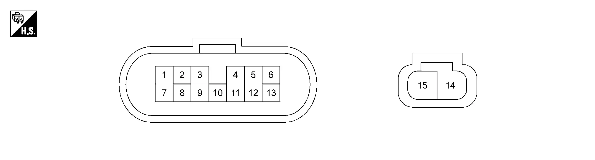
INPUT/OUTPUT SIGNAL STANDARD
|
Terminal No. (Wire color) | Description | Condition | Value (Approx.) | |||
|---|---|---|---|---|---|---|
| + | ŌłÆ | Signal | Input/Output | |||
|
1 (G) |
Ground | Battery | Input | Always | 10 ŌłÆ 16 V | |
|
2 (BR) |
Ground | Sensor power supply | Output | Ignition switch: ON | 5 V | |
| Ignition switch: OFF | 0 V | |||||
|
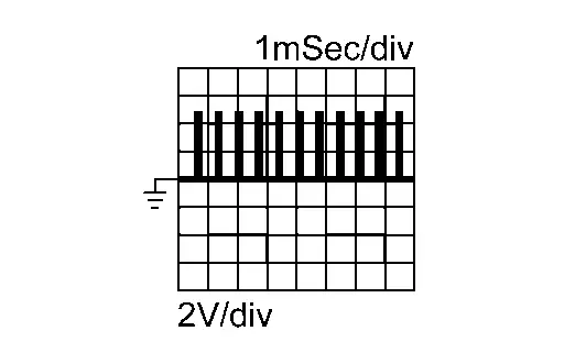
3 (Y) |
Ground | Primary speed sensor | Input |
|
1525 Hz
|
|
|
4 (R) |
Ground | CAN1-L | Input/Output | ŌĆö | ŌĆö | |
|
5 (R) |
Ground | CAN2-L | Input/Output | ŌĆö | ŌĆö | |
|
6 (B) |
Ground | Sensor ground | ŌĆö | Always | 0 V | |
|
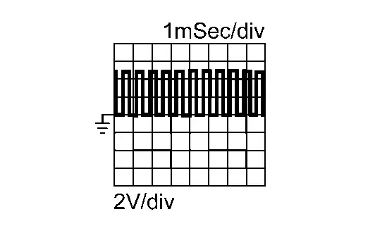
8 (LG) |
Ground | Input speed sensor | Input |
|
1525 Hz
|
|
|
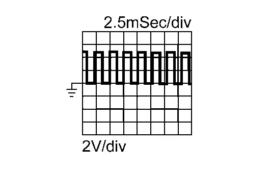
9 (L) |
Ground | Secondary speed sensor | Input |
|
360 Hz
|
|
|
10 (P) |
Ground | Ignition | Input/Output | ŌĆö | ŌĆö | |
|
11 (GR) |
Ground | CAN1-H | Input | ŌĆö | ŌĆö | |
|
12 (GR) |
Ground | CAN2-H | Input/Output | Ignition switch: ON | 10 ŌłÆ 16 V | |
| Ignition switch: OFF | 0 V | |||||
|
14 (W) |
Ground | Battery | Input | Always | 10 ŌłÆ 16 V | |
|
15 (B) |
Ground | Ground | ŌĆö | Always | 0 V | |
Fail-safe
Refer to Fail-safe.
Protection Control
Refer to Protection Control.
DTC Inspection Priority Chart
If multiple malfunction codes are detected at the same time, check each code according to the DTC check priority list below.
| Priority | DTC |
Items (CONSULT screen terms) | Reference | |
|---|---|---|---|---|
| 1 | P0863 | 00 | TCM communication | DTC Description |
| P18A5 | 00 | Auto park function cancellation | DTC Description | |
| U0073 | 00 | Control module communication bus A off | DTC Description | |
| U007A | 00 | Control module communication bus | DTC Description | |
| U0100 | 00 | Lost communication (ECM/PCM A) | DTC Description | |
| U0103 | 00 | Lost communication (gear shift control module A) | DTC Description | |
| U0115 | 00 | Lost communication (ECM/PCM B) | DTC Description | |
| U0122 | 00 | Lost communication [ABS actuator and electric unit (control unit)] | DTC Description | |
| U0140 | 00 | Lost communication (BCM) | DTC Description | |
| U0141 | 00 | Lost communication (BCM) A | DTC Description | |
| U0287 | 00 | Lost communication (transmission fluid pump module) | DTC Description | |
| U0300 | 00 | CAN communication data | DTC Description | |
| U1327 | 52 | MAC key update | DTC Description | |
| U1327 | 54 | MAC key update | DTC Description | |
| U1E05 | 00 | Lost communication [ABS actuator and electric unit (control unit)] | DTC Description | |
| U2140 | 57 | CAN communication error (ECM) | DTC Description | |
| U2140 | 87 | CAN communication error (ECM) | DTC Description | |
| U2148 | 87 | CAN communication error [ABS actuator and electric unit (control unit)] | DTC Description | |
| U214A | 87 | CAN communication error (AWD/4WD) | DTC Description | |
| U214F | 57 | CAN communication error (BCM) | DTC Description | |
| U214F | 87 | CAN communication error (BCM) | DTC Description | |
| U2152 | 57 | CAN communication error (ADAS control unit) | DTC Description | |
| U2152 | 87 | CAN communication error (ADAS control unit) | DTC Description | |
| U2153 | 87 | CAN communication error (HVAC) | DTC Description | |
| U215B | 87 | CAN communication error (IPDM E/R) | DTC Description | |
| U2176 | 57 | CAN communication error (chassis control module) | DTC Description | |
| U2240 | 87 | CAN communication error (ECM) | DTC Description | |
| U2247 | 87 | CAN communication error (electric shift control module) | DTC Description | |
| U2248 | 87 | CAN communication error [ABS actuator and electric unit (control unit)] | DTC Description | |
| U2252 | 87 | CAN communication error (ADAS control unit) | DTC Description | |
| U2276 | 87 | CAN communication error (chassis control module) | DTC Description | |
| 2 | P0740 | 00 | Torque converter clutch | DTC Description |
| P0742 | 00 | Torque converter clutch | DTC Description | |
| P0960 | 00 | Pressure control solenoid A | DTC Description | |
| P0962 | 00 | Pressure control solenoid A | DTC Description | |
| P0963 | 00 | Pressure control solenoid A | DTC Description | |
| P0964 | 00 | Pressure control solenoid B | DTC Description | |
| P0966 | 00 | Pressure control solenoid B | DTC Description | |
| P0967 | 00 | Pressure control solenoid B | DTC Description | |
| P0968 | 00 | Pressure control solenoid C | DTC Description | |
| P0970 | 00 | Pressure control solenoid C | DTC Description | |
| P0971 | 00 | Pressure control solenoid C | DTC Description | |
| P2769 | 00 | Torque converter clutch | DTC Description | |
| P2770 | 00 | Torque converter clutch | DTC Description | |
| P2812 | 00 | Pressure control solenoid G | DTC Description | |
| P2814 | 00 | Pressure control solenoid G | DTC Description | |
| P2815 | 00 | Pressure control solenoid G | DTC Description | |
| 3 | P0604 | 00 | Control module RAM | DTC Description |
| P0605 | 00 | Control module ROM | DTC Description | |
| P0606 | 00 | Control module | DTC Description | |
| P060A | 00 | Internal control module monitoring processor | DTC Description | |
| P062F | 00 | Control module EEPROM | DTC Description | |
| P0705 | 00 | Transmission range sensor A | DTC Description | |
| P0706 | 00 | Transmission range sensor A | DTC Description | |
| P0711 | 00 | Transmission fluid temperature sensor A | DTC Description | |
| P0712 | 00 | Transmission fluid temperature sensor A | DTC Description | |
| P0713 | 00 | Transmission fluid temperature sensor A | DTC Description | |
| P0715 | 00 | Input/Turbine shaft speed sensor A | DTC Description | |
| P0716 | 00 | Input/Turbine shaft speed sensor A | DTC Description | |
| P0717 | 00 | Input/Turbine shaft speed sensor A | DTC Description | |
| P0718 | 00 | Input/Turbine shaft speed sensor A | DTC Description | |
| P0780 | 00 | Shift error | DTC Description | |
| P0791 | 00 | Intermediate shaft speed sensor A | DTC Description | |
| P0792 | 00 | Intermediate shaft speed sensor A | DTC Description | |
| P0793 | 00 | Intermediate shaft speed sensor A | DTC Description | |
| P0794 | 00 | Intermediate shaft speed sensor A | DTC Description | |
| P07BF | 00 | Input/Turbine shaft speed sensor A | DTC Description | |
| P07C0 | 00 | Input/Turbine shaft speed sensor A | DTC Description | |
| P07C1 | 00 | Input/Turbine shaft speed sensor B | DTC Description | |
| P07C2 | 00 | Input/Turbine shaft speed sensor B | DTC Description | |
| P07C5 | 00 | Intermediate shaft speed sensor A | DTC Description | |
| P07C6 | 00 | Intermediate shaft speed sensor A | DTC Description | |
| P0840 | 00 | Transmission fluid pressure sensor/switch A | DTC Description | |
| P0846 | 00 | Transmission fluid pressure sensor/switch B | DTC Description | |
| P0847 | 00 | Transmission fluid pressure sensor/switch B | DTC Description | |
| P0848 | 00 | Transmission fluid pressure sensor/switch B | DTC Description | |
| P084A | 00 | Transmission fluid pressure sensor/switch H | DTC Description | |
| P084B | 00 | Transmission fluid pressure sensor/switch H | DTC Description | |
| P084C | 00 | Transmission fluid pressure sensor/switch H | DTC Description | |
| P084D | 00 | Transmission fluid pressure sensor/switch H | DTC Description | |
| P0870 | 00 | Transmission fluid pressure sensor/switch C | DTC Description | |
| P0871 | 00 | Transmission fluid pressure sensor/switch C | DTC Description | |
| P0872 | 00 | Transmission fluid pressure sensor/switch C | DTC Description | |
| P0873 | 00 | Transmission fluid pressure sensor/switch C | DTC Description | |
| P0890 | 00 | TCM | DTC Description | |
| P1588 | 00 | G sensor | DTC Description | |
| P159C | 00 | G sensor | DTC Description | |
| P159D | 00 | G sensor | DTC Description | |
| P188E | 00 | Electric oil pump | DTC Description | |
| P2765 | 00 | Input/Turbine shaft speed sensor B | DTC Description | |
| P2766 | 00 | Input/Turbine shaft speed sensor B | DTC Description | |
| P2767 | 00 | Input/Turbine shaft speed sensor B | DTC Description | |
| P2768 | 00 | Input/Turbine shaft speed sensor B | DTC Description | |
| P27B3 | 00 | Internal control module transmission gear select | DTC Description | |
| P27B5 | 00 | Internal control module transmission gear ratio control | DTC Description | |
| P27EB | 00 | Transmission range control A position sensor/switch | DTC Description | |
| P27EC | 00 | Transmission range control A position sensor/switch | DTC Description | |
| P27EF | 00 | Transmission range control B position sensor/switch | DTC Description | |
| P27F0 | 00 | Transmission range control B position sensor/switch | DTC Description | |
| 4 | P072A | 00 | Stuck in neutral | DTC Description |
| P0741 | 00 | Torque converter clutch | DTC Description | |
| P0746 | 00 | Pressure control solenoid A | DTC Description | |
| P0747 | 00 | Pressure control solenoid A | DTC Description | |
| P0776 | 00 | Pressure control solenoid B | DTC Description | |
| P0777 | 00 | Pressure control solenoid B | DTC Description | |
| P0796 | 00 | Pressure control solenoid C | DTC Description | |
| P0797 | 00 | Pressure control solenoid C | DTC Description | |
| P0961 | 00 | Pressure control solenoid A | DTC Description | |
| P17F0 | 07 | CVT judder (transmission Inspection) | DTC Description | |
| P17F1 | 07 | CVT judder (control valve inspection) | DTC Description | |
| P17F2 | 07 | CVT judder (torque converter inspection) | DTC Description | |
| P187E | 09 | Transmission system malfunction | DTC Description | |
| P18AB | 00 | Ignition switch | DTC Description | |
| P271E | 00 | Wheel torque calculation signal | DTC Description | |
| P27A1 | 00 | Electric/auxiliary transmission fluid pump A | DTC Description | |
| P27A3 | 00 | Electric/auxiliary transmission fluid pump B | DTC Description | |
| P27A4 | 00 | Electric/auxiliary transmission fluid pump B | DTC Description | |
| P27A5 | 00 | Electric/auxiliary transmission fluid pump B | DTC Description | |
| P27A6 | 00 | Electric/auxiliary transmission fluid pump B | DTC Description | |
| P2808 | 00 | Pressure control solenoid G | DTC Description | |
| P2809 | 00 | Pressure control solenoid G | DTC Description | |
| P28ED | 00 | Electric/auxiliary transmission fluid pump B | DTC Description | |
| P28EE | 00 | Electric/auxiliary transmission fluid pump B | DTC Description | |
| 5 | P06B1 | 00 | Sensor power supply A | DTC Description |
| P07E9 | 00 | Transmission range control A | DTC Description | |
| P07EA | 00 | Transmission range control A | DTC Description | |
| P07EB | 00 | Transmission range control A | DTC Description | |
| P07ED | 00 | Transmission range multi-function select | DTC Description | |
| P07EF | 00 | Transmission range multi-function select | DTC Description | |
| P07F2 | 00 | Transmission range control module communication | DTC Description | |
| P0914 | 00 | Gear shift position | DTC Description | |
| P0915 | 00 | Gear shift position | DTC Description | |
| P0919 | 00 | Gear shift position | DTC Description | |
| P272A | 00 | Transmission range select motor control | DTC Description | |
| P272B | 00 | Transmission range select motor control | DTC Description | |
| U0101 | 00 | Lost communication (TCM) | DTC Description | |
DTC Index
NOTE:
-
If multiple malfunction codes are detected at the same time, check each code according to the ŌĆ£DTC check priority listŌĆØ. DTC Inspection Priority Chart.
-
The ignition counter is displayed in ŌĆ£FFDŌĆØ. Refer to CONSULT Function.
├Ś:Applicable ŌĆö: Not applicable
| DTC*1, *2 |
Items (CONSULT screen terms) | Trip |
MIL *3 |
Electric shift warning lamp *4 |
CVT system warning *5 |
Electric shift warning *6 | Reference | ||
|---|---|---|---|---|---|---|---|---|---|
| GST |
CONSULT (TRANSMISSION) | ||||||||
| P0604 | P0604 | 00 | Control module RAM | 1 | ├Ś | ŌĆö | C | ŌĆö | DTC Description |
| P0605 | P0605 | 00 | Control module ROM | 1 | ├Ś | ŌĆö | C | ŌĆö | DTC Description |
| P0606 | P0606 | 00 | Control module processor | 1 | ├Ś | ŌĆö | C | ŌĆö | DTC Description |
| ŌĆö | P060A | 00 | Internal control module monitoring processor | 1 | ŌĆö | ŌĆö | ŌĆö | ŌĆö | DTC Description |
| P062F | P062F | 00 | Control module EEPROM | 1 | ├Ś | ŌĆö | A | ŌĆö | DTC Description |
| P06B1 | P06B1 | 00 | Sensor power supply A | 1 | ├Ś | ŌĆö | ŌĆö | ŌĆö | DTC Description |
| P0705 | P0705 | 00 | Transmission range sensor A | 2 | ├Ś | ŌĆö | C | ŌĆö | DTC Description |
| P0706 | P0706 | 00 | Transmission range sensor A | 2 | ├Ś | ŌĆö | C | ŌĆö | DTC Description |
| P0711 | P0711 | 00 | Transmission fluid temperature sensor A | 2 | ├Ś | ŌĆö | C | ŌĆö | DTC Description |
| P0712 | P0712 | 00 | Transmission fluid temperature sensor A | 2 | ├Ś | ŌĆö | C | ŌĆö | DTC Description |
| P0713 | P0713 | 00 | Transmission fluid temperature sensor A | 2 | ├Ś | ŌĆö | C | ŌĆö | DTC Description |
| P0715 | P0715 | 00 | Input/Turbine shaft speed sensor A | 2 | ├Ś | ŌĆö | C | ŌĆö | DTC Description |
| P0716 | P0716 | 00 | Input/Turbine shaft speed sensor A | 2 | ├Ś | ŌĆö | C | ŌĆö | DTC Description |
| P0717 | P0717 | 00 | Input/Turbine shaft speed sensor A | 2 | ├Ś | ŌĆö | C | ŌĆö | DTC Description |
| P0718 | P0718 | 00 | Input/Turbine shaft speed sensor A | 2 | ├Ś | ŌĆö | A | ŌĆö | DTC Description |
| P072A | P072A | 00 | Stuck in neutral | 1 | ├Ś | ŌĆö | ŌĆö | ŌĆö | DTC Description |
| P0740 | P0740 | 00 | Torque converter clutch | 2 | ├Ś | ŌĆö | C | ŌĆö | DTC Description |
| P0741 | P0741 | 00 | Torque converter clutch | 2 | ├Ś | ŌĆö | C | ŌĆö | DTC Description |
| P0742 | P0742 | 00 | Torque converter clutch | 1 | ├Ś | ŌĆö | B:Running A:Stopping | ŌĆö | DTC Description |
| P0746 | P0746 | 00 | Pressure control solenoid A | 2 | ├Ś | ŌĆö | C | ŌĆö | DTC Description |
| P0747 | P0747 | 00 | Pressure control solenoid A | 2 | ├Ś | ŌĆö | C | ŌĆö | DTC Description |
| P0776 | P0776 | 00 | Pressure control solenoid B | 2 | ├Ś | ŌĆö | C | ŌĆö | DTC Description |
| P0777 | P0777 | 00 | Pressure control solenoid B | 2 | ├Ś | ŌĆö | C | ŌĆö | DTC Description |
| P0780 | P0780 | 00 | Shift error | 1 | ├Ś | ├Ś [Less than 5 km/h(3 MPH)] |
B:Running A:Stopping [Less than 7.5 km/h(4.7 MPH)] |
├Ś [Less than 5 km/h(3 MPH)] | DTC Description |
| P0791 | P0791 | 00 | Intermediate shaft speed sensor A | 2 | ├Ś | ŌĆö | C | ŌĆö | DTC Description |
| P0792 | P0792 | 00 | Intermediate shaft speed sensor A | 2 | ├Ś | ŌĆö | C | ŌĆö | DTC Description |
| P0793 | P0793 | 00 | Intermediate shaft speed sensor A | 2 | ├Ś | ŌĆö | C | ŌĆö | DTC Description |
| P0794 | P0794 | 00 | Intermediate shaft speed sensor A | 2 | ├Ś | ŌĆö | A | ŌĆö | DTC Description |
| P0796 | P0796 | 00 | Pressure control solenoid C | 2 | ├Ś | ŌĆö | C | ŌĆö | DTC Description |
| P0797 | P0797 | 00 | Pressure control solenoid C | 2 | ├Ś | ŌĆö | C | ŌĆö | DTC Description |
| P07BF | P07BF | 00 | Input/Turbine shaft speed sensor A | 2 | ├Ś | ŌĆö | C | ŌĆö | DTC Description |
| P07C0 | P07C0 | 00 | Input/Turbine shaft speed sensor A | 2 | ├Ś | ŌĆö | C | ŌĆö | DTC Description |
| P07C1 | P07C1 | 00 | Input/Turbine shaft speed sensor B | 2 | ├Ś | ŌĆö | C | ŌĆö | DTC Description |
| P07C2 | P07C2 | 00 | Input/Turbine shaft speed sensor B | 2 | ├Ś | ŌĆö | C | ŌĆö | DTC Description |
| P07C5 | P07C5 | 00 | Intermediate shaft speed sensor A | 2 | ├Ś | ŌĆö | C | ŌĆö | DTC Description |
| P07C6 | P07C6 | 00 | Intermediate shaft speed sensor A | 2 | ├Ś | ŌĆö | C | ŌĆö | DTC Description |
| P07E9 | P07E9 | 00 | Transmission range control A | 1 | ├Ś | ŌĆö | ŌĆö | ŌĆö | DTC Description |
| P07EA | P07EA | 00 | Transmission range control A | 1 | ├Ś | ŌĆö | ŌĆö | ŌĆö | DTC Description |
| P07EB | P07EB | 00 | Transmission range control A | 1 | ├Ś | ŌĆö | ŌĆö | ŌĆö | DTC Description |
| P07ED | P07ED | 00 | Transmission range multi-function select | 1 | ├Ś | ŌĆö | ŌĆö | ŌĆö | DTC Description |
| P07EF | P07EF | 00 | Transmission range multi-function select | 1 | ├Ś | ŌĆö | ŌĆö | ŌĆö | DTC Description |
| P07F2 | P07F2 | 00 | Transmission range control module communication | 1 | ├Ś | ŌĆö | ŌĆö | ŌĆö | DTC Description |
| P0840 | P0840 | 00 | Transmission fluid pressure sensor/switch A | 2 | ├Ś | ŌĆö | A | ŌĆö | DTC Description |
| P0846 | P0846 | 00 | Transmission fluid pressure sensor/switch B | 2 | ├Ś | ŌĆö | A | ŌĆö | DTC Description |
| P0847 | P0847 | 00 | Transmission fluid pressure sensor/switch B | 2 | ├Ś | ŌĆö | A | ŌĆö | DTC Description |
| P0848 | P0848 | 00 | Transmission fluid pressure sensor/switch B | 2 | ├Ś | ŌĆö | A | ŌĆö | DTC Description |
| P084A | P084A | 00 | Transmission fluid pressure sensor/switch H | 2 | ├Ś | ŌĆö | A | ŌĆö | DTC Description |
| P084B | P084B | 00 | Transmission fluid pressure sensor/switch H | 2 | ├Ś | ŌĆö | A | ŌĆö | DTC Description |
| P084C | P084C | 00 | Transmission fluid pressure sensor/switch H | 2 | ├Ś | ŌĆö | A | ŌĆö | DTC Description |
| P084D | P084D | 00 | Transmission fluid pressure sensor/switch H | 2 | ├Ś | ŌĆö | A | ŌĆö | DTC Description |
| P0863 | P0863 | 00 | TCM communication | 1 | ├Ś | ŌĆö | C | ŌĆö | DTC Description |
| P0870 | P0870 | 00 | Transmission fluid pressure sensor/switch C | 2 | ├Ś | ŌĆö | A | ŌĆö | DTC Description |
| P0871 | P0871 | 00 | Transmission fluid pressure sensor/switch C | 2 | ├Ś | ŌĆö | A | ŌĆö | DTC Description |
| P0872 | P0872 | 00 | Transmission fluid pressure sensor/switch C | 2 | ├Ś | ŌĆö | A | ŌĆö | DTC Description |
| P0873 | P0873 | 00 | Transmission fluid pressure sensor/switch C | 2 | ├Ś | ŌĆö | A | ŌĆö | DTC Description |
| P0890 | P0890 | 00 | TCM | 1 | ├Ś | ŌĆö | C | ŌĆö | DTC Description |
| P0914 | P0914 | 00 | Gear shift position | 2 | ├Ś | ŌĆö | ŌĆö | ŌĆö | DTC Description |
| P0915 | P0915 | 00 | Gear shift position | 1 | ├Ś | ŌĆö | ŌĆö | ŌĆö | DTC Description |
| P0919 | P0919 | 00 | Gear shift position | 1 | ├Ś | ŌĆö | ŌĆö | ŌĆö | DTC Description |
| P0960 | P0960 | 00 | Pressure control solenoid A | 2 | ├Ś | ŌĆö | C | ŌĆö | DTC Description |
| P0961 | P0961 | 00 | Pressure control solenoid A | 2 | ├Ś | ŌĆö | C | ŌĆö | DTC Description |
| P0962 | P0962 | 00 | Pressure control solenoid A | 2 | ├Ś | ŌĆö | C | ŌĆö | DTC Description |
| P0963 | P0963 | 00 | Pressure control solenoid A | 2 | ├Ś | ŌĆö | C | ŌĆö | DTC Description |
| P0964 | P0964 | 00 | Pressure control solenoid B | 2 | ├Ś | ŌĆö | C | ŌĆö | DTC Description |
| P0966 | P0966 | 00 | Pressure control solenoid B | 2 | ├Ś | ŌĆö | C | ŌĆö | DTC Description |
| P0967 | P0967 | 00 | Pressure control solenoid B | 2 | ├Ś | ŌĆö | C | ŌĆö | DTC Description |
| P0968 | P0968 | 00 | Pressure control solenoid C | 2 | ├Ś | ŌĆö | C | ŌĆö | DTC Description |
| P0970 | P0970 | 00 | Pressure control solenoid C | 2 | ├Ś | ŌĆö | C | ŌĆö | DTC Description |
| P0971 | P0971 | 00 | Pressure control solenoid C | 2 | ├Ś | ŌĆö | C | ŌĆö | DTC Description |
| P1588 | P1588 | 00 | G sensor | 2 | ├Ś | ŌĆö | ŌĆö | ŌĆö | DTC Description |
| P159C | P159C | 00 | G sensor | 2 | ├Ś | ŌĆö | ŌĆö | ŌĆö | DTC Description |
| P159D | P159D | 00 | G sensor | 2 | ├Ś | ŌĆö | ŌĆö | ŌĆö | DTC Description |
| ŌĆö | P17F0 | 07 | CVT judder (transmission Inspection) | 1 | ŌĆö | ŌĆö | ŌĆö | ŌĆö | DTC Description |
| ŌĆö | P17F1 | 07 | CVT judder (control valve inspection) | 1 | ŌĆö | ŌĆö | ŌĆö | ŌĆö | DTC Description |
| ŌĆö | P17F2 | 07 | CVT judder (torque converter inspection) | 1 | ŌĆö | ŌĆö | ŌĆö | ŌĆö | DTC Description |
| ŌĆö | P187E | 09 | Transmission system malfunction | ŌĆö | ŌĆö | ŌĆö | ŌĆö | ŌĆö | DTC Description |
| P188E | P188E | 00 | Electric oil pump | 2 | ├Ś | ŌĆö | A | ŌĆö | DTC Description |
| ŌĆö | P18A5 | 00 | Auto park function cancellation | 1 | ŌĆö |
├Ś (Blink) |
ŌĆö | ŌĆö | DTC Description |
| ŌĆö | P18AB | 00 | Ignition switch | 1 | ŌĆö | ├Ś [Less than 5 km/h(3 MPH)] | A [Less than 5 km/h(3 MPH)] | ├Ś [Less than 5 km/h(3 MPH)] | DTC Description |
| ŌĆö | P271E | 00 | Wheel torque calculation signal | 1 | ŌĆö | ŌĆö | ŌĆö | ŌĆö | DTC Description |
| P272A | P272A | 00 | Transmission range select motor control | 1 | ├Ś | ŌĆö | ŌĆö | ŌĆö | DTC Description |
| P272B | P272B | 00 | Transmission range select motor control | 1 | ├Ś | ŌĆö | ŌĆö | ŌĆö | DTC Description |
| P2765 | P2765 | 00 | Input/Turbine shaft speed sensor B | 2 | ├Ś | ŌĆö | C | ŌĆö | DTC Description |
| P2766 | P2766 | 00 | Input/Turbine shaft speed sensor B | 2 | ├Ś | ŌĆö | C | ŌĆö | DTC Description |
| P2767 | P2767 | 00 | Input/Turbine shaft speed sensor B | 2 | ├Ś | ŌĆö | C | ŌĆö | DTC Description |
| P2768 | P2768 | 00 | Input/Turbine shaft speed sensor B | 2 | ├Ś | ŌĆö | A | ŌĆö | DTC Description |
| P2769 | P2769 | 00 | Torque converter clutch | 2 | ├Ś | ŌĆö | C | ŌĆö | DTC Description |
| P2770 | P2770 | 00 | Torque converter clutch | 2 | ├Ś | ŌĆö | B:Running A:Stopping | ŌĆö | DTC Description |
| P27A1 | P27A1 | 00 | Electric/auxiliary transmission fluid pump A | 2 | ├Ś | ŌĆö | A | ŌĆö | DTC Description |
| P27A3 | P27A3 | 00 | Electric/auxiliary transmission fluid pump B | 2 | ├Ś | ŌĆö | A | ŌĆö | DTC Description |
| P27A4 | P27A4 | 00 | Electric/auxiliary transmission fluid pump B | 2 | ├Ś | ŌĆö | A | ŌĆö | DTC Description |
| ŌĆö | P27A5 | 00 | Electric/auxiliary transmission fluid pump B | 1 | ŌĆö | ŌĆö | ŌĆö | ŌĆö | DTC Description |
| P27A6 | P27A6 | 00 | Electric/auxiliary transmission fluid pump B | 2 | ├Ś | ŌĆö | C | ŌĆö | DTC Description |
| P27B3 | P27B3 | 00 | Internal control module transmission gear select | 1 | ├Ś | ŌĆö | B:Running A:Stopping | ŌĆö | DTC Description |
| ŌĆö | P27B5 | 00 | Internal control module transmission gear ratio control | 1 | ŌĆö | ŌĆö | A | ŌĆö | DTC Description |
| P27EB | P27EB | 00 | Transmission range control A position sensor/switch | 2 | ├Ś | ŌĆö | C | ŌĆö | DTC Description |
| P27EC | P27EC | 00 | Transmission range control A position sensor/switch | 2 | ├Ś | ŌĆö | C | ŌĆö | DTC Description |
| P27EF | P27EF | 00 | Transmission range control B position sensor/switch | 2 | ├Ś | ŌĆö | C | ŌĆö | DTC Description |
| P27F0 | P27F0 | 00 | Transmission range control B position sensor/switch | 2 | ├Ś | ŌĆö | C | ŌĆö | DTC Description |
| P2808 | P2808 | 00 | Pressure control solenoid G | 2 | ├Ś | ŌĆö | B:Running A:Stopping | ŌĆö | DTC Description |
| P2809 | P2809 | 00 | Pressure control solenoid G | 2 | ├Ś | ŌĆö | C | ŌĆö | DTC Description |
| P2812 | P2812 | 00 | Pressure control solenoid G | 2 | ├Ś | ŌĆö | C | ŌĆö | DTC Description |
| P2814 | P2814 | 00 | Pressure control solenoid G | 2 | ├Ś | ŌĆö | C | ŌĆö | DTC Description |
| P2815 | P2815 | 00 | Pressure control solenoid G | 2 | ├Ś | ŌĆö | B:Running A:Stopping | ŌĆö | DTC Description |
| P28ED | P28ED | 00 | Electric/auxiliary transmission fluid pump B | 2 | ├Ś | ŌĆö | A | ŌĆö | DTC Description |
| P28EE | P28EE | 00 | Electric/auxiliary transmission fluid pump B | 2 | ├Ś | ŌĆö | A | ŌĆö | DTC Description |
| U0073 | U0073 | 00 | Control module communication bus A off | 1 | ├Ś | ŌĆö | ŌĆö | ŌĆö | DTC Description |
| U007A | U007A | 00 | Control module communication bus | 1 | ├Ś | ŌĆö | ŌĆö | ŌĆö | DTC Description |
| U0100 | U0100 | 00 | Lost communication (ECM/PCM A) | 1 | ├Ś | ŌĆö | ŌĆö | ŌĆö | DTC Description |
| U0101 | U0101 | 00 | Lost communication (TCM) | 2 | ├Ś | ŌĆö | ŌĆö | ŌĆö | DTC Description |
| U0103 | U0103 | 00 | Lost communication (gear shift control module A) | 1 | ├Ś |
├Ś [Less than 5 km/h(3 MPH)] |
B:Running A:Stopping [Less than 7.5 km/h(4.7 MPH)] |
├Ś [Less than 5 km/h(3 MPH)] |
DTC Description |
| U0115 | U0115 | 00 | Lost communication (ECM/PCM B) | 1 | ├Ś | ŌĆö | ŌĆö | ŌĆö | DTC Description |
| U0122 | U0122 | 00 | Lost communication [ABS actuator and electric unit (control unit)] | 2 | ├Ś | ŌĆö | ŌĆö | ŌĆö | DTC Description |
| ŌĆö | U0140 | 00 | Lost communication (BCM) | 1 | ŌĆö | ŌĆö | ŌĆö | ŌĆö | DTC Description |
| ŌĆö | U0141 | 00 | Lost communication (BCM) A | 1 | ŌĆö | ŌĆö | ŌĆö | ŌĆö | DTC Description |
| U0287 | U0287 | 00 | Lost communication (transmission fluid pump module) | 2 | ├Ś | ŌĆö | A | ŌĆö | DTC Description |
| ŌĆö | U0300 | 00 | CAN communication data | 1 | ŌĆö | ŌĆö | ŌĆö | ŌĆö | DTC Description |
| ŌĆö | U1327 | 52 | MAC key update | 1 | ŌĆö | ŌĆö | ŌĆö | ŌĆö | DTC Description |
| ŌĆö | U1327 | 54 | MAC key update | 1 | ŌĆö | ŌĆö | ŌĆö | ŌĆö | DTC Description |
| ŌĆö | U1E05 | 00 | Lost communication [ABS actuator and electric unit (control unit)] | 1 | ŌĆö | ŌĆö | ŌĆö | ŌĆö | DTC Description |
| ŌĆö | U2140 | 57 | CAN communication error (ECM) | 1 | ŌĆö | ŌĆö | ŌĆö | ŌĆö | DTC Description |
| ŌĆö | U2140 | 87 | CAN communication error (ECM) | 1 | ŌĆö | ŌĆö | ŌĆö | ŌĆö | DTC Description |
| ŌĆö | U2148 | 87 | CAN communication error [ABS actuator and electric unit (control unit)] | 1 | ŌĆö | ŌĆö | ŌĆö | ŌĆö | DTC Description |
| ŌĆö | U214A | 87 | CAN communication error (AWD/4WD) | 1 | ŌĆö | ŌĆö | ŌĆö | ŌĆö | DTC Description |
| ŌĆö | U214F | 57 | CAN communication error (BCM) | 1 | ŌĆö | ŌĆö | ŌĆö | ŌĆö | DTC Description |
| ŌĆö | U214F | 87 | CAN communication error (BCM) | 1 | ŌĆö | ŌĆö | ŌĆö | ŌĆö | DTC Description |
| ŌĆö | U2152 | 57 | CAN communication error (ADAS control unit) | 1 | ŌĆö | ŌĆö | ŌĆö | ŌĆö | DTC Description |
| ŌĆö | U2152 | 87 | CAN communication error (ADAS control unit) | 1 | ŌĆö | ŌĆö | ŌĆö | ŌĆö | DTC Description |
| ŌĆö | U2153 | 87 | CAN communication error (HVAC) | 1 | ŌĆö | ŌĆö | ŌĆö | ŌĆö | DTC Description |
| ŌĆö | U215B | 87 | CAN communication error (IPDM E/R) | 1 | ŌĆö | ŌĆö | ŌĆö | ŌĆö | DTC Description |
| ŌĆö | U2176 | 57 | CAN communication error (chassis control module) | 1 | ŌĆö | ŌĆö | ŌĆö | ŌĆö | DTC Description |
| ŌĆö | U2240 | 87 | CAN communication error (ECM) | 1 | ŌĆö | ŌĆö | ŌĆö | ŌĆö | DTC Description |
| ŌĆö | U2247 | 87 | CAN communication error (electric shift control module) | 1 | ŌĆö | ŌĆö | ŌĆö | ŌĆö | DTC Description |
| ŌĆö | U2248 | 87 | CAN communication error [ABS actuator and electric unit (control unit)] | 1 | ŌĆö | ŌĆö | ŌĆö | ŌĆö | DTC Description |
| ŌĆö | U2252 | 87 | CAN communication error (ADAS control unit) | 1 | ŌĆö | ŌĆö | ŌĆö | ŌĆö | DTC Description |
| ŌĆö | U2276 | 87 | CAN communication error (chassis control module) | 1 | ŌĆö | ŌĆö | ŌĆö | ŌĆö | DTC Description |
*1: These numbers are specified by SAE J2012/ISO 15031-6.
*2: The DTC number of the 1st trip is the same as the DTC number.
*3: Refer to Malfunction Indicator Lamp (MIL).
*4: Refer to Electric Shift Warning Lamp (FULL TFT METER) or Electric Shift Warning Lamp (7 INCH INFORMATION DISPLAY).
*5: Refer to CVT System Warning.
*6: Refer to Electric Shift Warning
Other materials:
Symptom Diagnosis. Door Does Not Lock/unlock with Intelligent Key (one Key)
Description
All doors do not lock/unlock using Intelligent Key button. (One Intelligent Key has the symptom, other keys operate normally.)NOTE:
Before starting diagnosis check that vehicle condition is
as shown in ŌĆ£Conditions of Nissan Ariya vehicleŌĆØ, and check each
symptom.
SYMPTOM TABLE ...
System Description. Component Parts. Moonroof System
Moonroof System
Component Description
No. Component Function
1.
Moonroof switch assembly
Refer to Moonroof Switch Assembly.
2.
Moonroof motor assembly
Refer to Moonroof Motor Assembly.
3.
Front door lock assembly RH (door switch)
Detects door open/close condition ...
Intelligent Lane Intervention (I-LI)
Basic information
WARNING
The Intelligent Lane Intervention system on the Nissan Rogue must be used with caution. Ignoring warnings or relying solely on the system may lead to loss of control, injury or death.
I-LI will not steer the Nissan Rogue for you or prevent skidding. The driver must alwa ...