Nissan Rogue (T33) 2021-Present Service Manual: Ecu Diagnosis Information :: Power Window Main Switch
Reference Value
TERMINAL LAYOUT

PHYSICAL VALUES
|
Terminal No. (Wire color) | Description | Condition |
Value (Approx.) | |||
|---|---|---|---|---|---|---|
| (+) | (–) | Signal name | Input/Output | |||
|
2*1 (R) |
Ground | Down mirror motor sensor power supply | Input | — | 5 V | |
|
3 (G) |
Ground | Auto ACC power supply | Input | Ignition switch OFF (auto ACC status) or ON | Battery voltage | |
|
4 (L) |
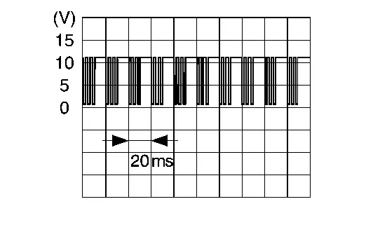
Ground | LIN communication signal | Input/ Output | Ignition switch ON |
|
|
|
5 (BG) |
Ground | Front power window motor (passenger side) UP signal | Output | Power window main switch (passenger side switch) | Operate (UP) | 0 V |
| Other than above | Battery voltage | |||||
|
6 (V) |
Ground | Door mirror motor (driver side) UP output signal | Output | Door mirror LH | Operate (UP) | Battery voltage |
| Other than above | 0 V | |||||
|
7 (GR)*1 (P)*2 |
Ground | Door mirror sensor (driver side) UP/DOWN signal*1 | Output | Door mirror LH position | Change between 5 V (close to peak) - 2 V (close to valley) | |
| Door mirror motor (passenger side) DOWN/RIGHT output signal*2 | Door mirror RH position | Operate (DOWN/RIGHT) | Battery voltage | |||
| Other than above | 0 V | |||||
|
8 (P)*1 (GR)*2 |
Ground | Door mirror sensor (driver side) LEFT/RIGHT signal*1 | Output | Door mirror LH position | 3 V | |
| Door mirror motor (passenger side) UP output signal*2 | Door mirror RH position | Operate (UP) | Battery voltage | |||
| Other than above | 0 V | |||||
|
9*2 (Y) |
Ground | Door mirror motor (passenger side) LEFT output signal | Output | Door mirror RH | Operate (LEFT) | Battery voltage |
| Other than above | 0 V | |||||
|
10 (BG) |
Ground | Door mirror motor (driver side) LEFT output signal | Output | Door mirror LH | Operate (LEFT) | Battery voltage |
| Other than above | 0 V | |||||
|
11 (W) |
Ground | Rear power window„ÄÄmotor RH DOWN signal | Output | Power window main switch (rear RH switch) | Operate (DOWN) | 0 V |
| Other than above | Battery voltage | |||||
|
12 (V) |
Ground | Power window lock signal | Output | Power window main switch (window lock switch) Operate | 0 V | |
|
13 (Y) |
Ground | Front power window motor (driver side) DOWN signal (for submersion) | Output | Ignition switch OFF (auto ACC status) or ON | Battery voltage | |
| Ignition switch OFF (not auto ACC status) | 0 V | |||||
|
14*1 (W) |
Ground | Ground (door mirror sensor) | — | — | 0 V | |
|
15 (BR) |
Ground | Front power window motor (passenger side) DOWN signal | Output | Power window main switch (passenger side switch) | Operate (DOWN) | 0 V |
| Other than above | Battery voltage | |||||
|
16 (LG) |
Ground | Rear power window motor RH UP signal | Output | Power window main switch (rear RH switch) | Operate (UP) | 0 V |
| Other than above | Battery voltage | |||||
|
21 (L) |
Ground | Door mirror motor (driver side) DOWN/RIGHT output signal | Output | Door mirror LH | Operate (DOWN/RIGHT) | Battery voltage |
| Other than above | 0 V | |||||
|
22 (B) |
Ground | Ground | — | — | 0 V | |
|
23 (SB) |
Ground | Rear power window motor LH DOWN signal | Output | Power window main switch (rear LH switch) | Operate (DOWN) | 0 V |
| Other than above | Battery voltage | |||||
|
24 (P) |
Ground | Rear power window motor LH UP signal | Output | Power window main switch (rear LH switch) | Operate (UP) | 0 V |
| Other than above | Battery voltage | |||||
*1: With automatic drive positioner
*2: Without automatic drive positioner
Other materials:
Cvt: Ge0f14a. Symptom Diagnosis
Cvt Control System
Symptom Table
The diagnosis item number indicates the order of check. Start checking in the order from 1.
Perform diagnoses of symptom table 1 before symptom table 2.
Symptom Table 1 Diagnostic item Reference Symptom
Shift Shock Slips/Will Not Engage Other
...
Fonctionnement du système LDW
Témoin LDW (affiché sur l’écran d’informations du véhicule)
Écran d’informations du véhicule
Commandes au volant (côté gauche)
Le système LDW du Nissan Rogue active la fonction d’alerte sortie de voie lorsque la vitesse du véhicule atteint environ 60 km/h (37 mi ...
Transaxle Assembly
Exploded View
O-ring
Tube A
Control valve
O-ring
Oil strainer
Oil pan gasket
Oil pan
Drain plug gasket
Drain plug
Magnet
O-ring
O-ring
Tube B
Lip seal
Transaxle assembly
: Always replace after every disassembly ...