Nissan Rogue (T33) 2021-Present Service Manual: Ecu Diagnosis Information :: Bcm
Values on the Diagnosis Tool
 NOTE:
NOTE:
The following table includes information (items) inapplicable to this Nissan Ariya vehicle. For information (items) applicable to this vehicle, refer to CONSULT display items.
| Monitor Item | Condition | Value/Status |
|---|---|---|
| Set switch | TPMS reset switch not depressed | Off |
| TPMS reset switch depressed | On | |
| Tire status-front left | Displays front tire LH status | Normal |
| MALF 1 | ||
| MALF 2 | ||
| MALF 3 | ||
| MALF 4 | ||
| Tire status-front right | Displays front tire RH status | Normal |
| MALF 1 | ||
| MALF 2 | ||
| MALF 3 | ||
| MALF 4 | ||
| Tire status-rear right | Displays rear tire RH status | Normal |
| MALF 1 | ||
| MALF 2 | ||
| MALF 3 | ||
| MALF 4 | ||
| Tire status-rear left | Displays rear tire LH status | Normal |
| MALF 1 | ||
| MALF 2 | ||
| MALF 3 | ||
| MALF 4 | ||
| Nissan Ariya Vehicle speed | Display the vehicle speed | (mph/km/h) |
| Set temperature-front left | Displays standard temperature of the front tire LH | ┬░F/┬░C |
| Set temperature-front right | Displays standard temperature of the front tire RH | |
| Set temperature-rear right | Displays standard temperature of the rear tire RH | |
| Set temperature-rear left | Displays standard temperature of the rear tire LH | |
| Tire internal temperature-front left | Displays temperature of the front tire LH | ┬░F/┬░C |
| Tire internal temperature-front right | Displays temperature of the front tire RH | |
| Tire internal temperature-rear right | Displays temperature of the rear tire RH | |
| Tire internal temperature-rear left | Displays temperature of the rear tire LH | |
| Warning air pressure-front left | Displays warning air pressure of the front tire LH | psi/mBar |
| Warning air pressure-front right | Displays warning air pressure of the front tire RH | |
| Warning air pressure-rear right | Displays warning air pressure of the rear tire RH | |
| Warning air pressure-rear left | Displays warning air pressure of the rear tire LH | |
| Set air pressure 1-front left | Displays standard air pressure of the front tire LH | psi/mBar |
| Set air pressure 1-front right | Displays standard air pressure of the front tire RH | |
| Set air pressure 1ŌĆōrear right | Displays standard air pressure of the rear tire RH | |
| Set air pressure 1 rear left | Displays standard air pressure of the rear tire LH | |
| Set air pressure 2-front left | Displays standard air pressure of the front tire LH | psi/mBar |
| Set air pressure 2-front right | Displays standard air pressure of the front tire RH | |
| Set air pressure 2ŌĆōrear right | Displays the standard air pressure of rear tire RH | |
| Set air pressure 2-rear left | Displays standard air pressure of the rear tire LH | |
| Air pressure-front left | Displays air pressure of the front tire LH | psi/mBar |
| Air pressure-front right | Displays air pressure of the front tire RH | |
| Air pressure-rear right | Displays air pressure of the rear tire RH | |
| Air pressure-rear left | Displays air pressure of the rear tire LH | |
| Door switch driver | Front door LH closed | Off |
| Front door LH opened | On | |
| Door switch assist | Front door RH closed | Off |
| Front door RH opened | On | |
| Door switch rear left | Rear door LH closed | Off |
| Rear door LH opened | On | |
| Door switch rear right | Rear door RH closed | Off |
| Rear door RH opened | On | |
| Door lock and unlock switch (lock) | Any position other than LOCK | Off |
| Door lock/unlock switch LOCK position | On | |
| Door lock and unlock switch (unlock) | Any position other than UNLOCK | Off |
| Door lock/unlock switch UNLOCK position | On | |
| Ignition switch |
This item is displayed, but cannot be monitored |
Off |
| On | ||
| START SW |
This item is displayed, but cannot be monitored |
Off |
| On | ||
| ECO mode switch | Other than drive mode select switch ECO mode position | Off |
| Drive mode select switch ECO mode position | On | |
| Sport mode switch | Other than drive mode select switch SPORT mode position | Off |
| Drive mode select switch SPORT mode position | On | |
| Drive mode SW comm | Drive mode switch communicating via LIN communication | No error |
| Drive mode switch not communicating via LIN communication | Error | |
| Battery voltage (door lock 1) | Battery power supply (front door lock) OFF | Off |
| Battery power supply (front door lock) ON | On | |
| Battery voltage (door lock 2) | Battery power supply (rear door lock) OFF | Off |
| Battery power supply (rear door lock) ON | On | |
| Battery voltage (electric control unit) | Battery power supply OFF | Off |
| Battery power supply ON | On | |
| Battery voltage (flasher) | Battery power supply (turn signal lamp) OFF | Off |
| Battery power supply (turn signal lamp) ON | On | |
| Battery voltage (stop lamp) | Battery power supply (stop lamp) OFF | Off |
| Battery power supply (stop lamp) ON | On | |
| Battery voltage (wiper) | Battery power supply (rear wiper) OFF | Off |
| Battery power supply (rear wiper) ON | On | |
| Seat belt switch (driver) | Front seat belt LH is released | Off |
| Front seat belt LH is fastened | On | |
| Rear wiper auto stop switch | Any position other than rear wiper stop position | Off |
| When rear wiper stop position | On | |
| Back-up lamp output | Shift selector R range | On |
| Shift selector other than R range | Off | |
| Back door/trunk |
This item is displayed, but cannot be monitored |
On |
| Off | ||
| Optical sensor | Display the value of outside brightness input from the optical sensor | ŌĆö |
| Check diode 1 | Combination switch check diode 1 OFF | Off |
| Combination switch check diode 1 ON | On | |
| High beam switch | Any position other than lighting switch high beam | Off |
| Lighting switch high beam position | On | |
| Passing switch | Any position other than lighting switch passing | Off |
| Lighting switch passing position | On | |
| Rear fog switch |
This item is displayed, but cannot be monitored |
Off |
| On | ||
| Front fog switch | Any position other than lighting switch front fog | Off |
| Lighting switch front fog position | On | |
| INT volume 1 | Combination switch INT volume 1 OFF | Off |
| Combination switch INT volume 1 ON | On | |
| Check diode 2 | Combination switch check diode 2 OFF | Off |
| Combination switch check diode 2 ON | On | |
| Low beam switch | Any position other than lighting switch 1ST | Off |
| Lighting switch 1ST position | On | |
| AUTO light switch | Any position other than lighting switch AUTO light | Off |
| Lighting switch AUTO light position | On | |
| High beam assist switch | Any position other than lighting switch high beam assist | Off |
| Lighting switch high beam assist position | On | |
| Tail lamp switch | Any position other than lighting switch 1ST | Off |
| Lighting switch 1ST position | On | |
| Front washer switch | Any position other than washer switch front washer | Off |
| Washer switch front washer position | On | |
| Rear washer switch | Any position other than washer switch rear washer | Off |
| Washer switch rear washer position | On | |
| Check diode 3 | Combination switch check diode 3 OFF | Off |
| Combination switch check diode 3 ON | On | |
| Turn signal LH | Any position other than turn signal switch turn signal LH | Off |
| Turn signal switch turn signal LH position | On | |
| Turn signal RH | Any position other than turn signal switch turn signal RH | Off |
| turn signal switch turn signal RH position | On | |
| Front wiper LO | Any position other than wiper switch front wiper LO | Off |
| Wiper switch front wiper LO position | On | |
| Front wiper HI | Any position other than wiper switch front wiper HI | Off |
| Wiper switch front wiper HI position | On | |
| Front wiper INT | Any position other than wiper switch front wiper INT | Off |
| Wiper switch front wiper INT position | On | |
| Check diode 4 | Combination switch check diode 4 OFF | Off |
| Combination switch check diode 4 ON | On | |
| Light OFF switch | Any position other than lighting switch light OFF | Off |
| Lighting switch light OFF position | On | |
| INT volume 2 | Combination switch INT volume 2 OFF | Off |
| Combination switch INT volume 2 ON | On | |
| INT volume 3 | Combination switch INT volume 3 OFF | Off |
| Combination switch INT volume 3 ON | On | |
| Rear wiper INT | Combination switch rear wiper INT OFF | Off |
| Combination switch rear wiper INT ON | On | |
| Rear wiper ON | Any position other than wiper switch rear wiper ON | Off |
| Wiper switch rear wiper switch ON position | On | |
| Check diode 5 | Combination switch check diode 5 OFF | Off |
| Combination switch check diode 5 ON | On | |
| Front wiper OFF | Any position other than wiper switch front wiper OFF | Off |
| Wiper switch front wiper OFF position | On | |
| Front wiper MIST | Any position other than wiper switch front wiper MIST | Off |
| Wiper switch front wiper MIST position | On | |
| Hazard switch | Hazard switch not depressed | Off |
| Hazard switch depressed | On | |
| Alcoholic interlock device permission status | Permission | On |
| No permission | Off | |
| Malfunction | NG | |
| Paddle shift switch (-) | Paddle shifter (shift down switch) not depressed | Off |
| Paddle shifter (shift down switch) depressed | On | |
| Paddle shift switch (+) | Paddle shifter (shift up switch) not depressed | Off |
| Paddle shifter (shift up switch) depressed | On | |
| Clutch end switch |
This item is displayed, but cannot be monitored |
Off |
| On | ||
| Clutch start switch |
This item is displayed, but cannot be monitored |
Off |
| On | ||
| Stop/start switch |
This item is displayed, but cannot be monitored |
Off |
| On | ||
| Detention/Cancel switch |
This item is displayed, but cannot be monitored |
Off |
| On | ||
| Brake switch 1 | Brake pedal depressed | Off |
| Brake pedal not depressed | On | |
| Brake switch 2 | Brake pedal not depressed | Off |
| Brake pedal depressed | On | |
| Back door/trunk opener switch |
This item is displayed, but cannot be monitored |
Off |
| On | ||
| Request switch back door/trunk lid | Back door opener switch (request switch) not pressed | Off |
| Back door opener switch (request switch) pressed | On | |
| Back door/trunk lid switch | Back door closed | Off |
| Back door opened | On | |
| Back door/trunk status | Back door closed | Close |
| Back door opened | Open | |
| Unlock sensor | Front door LH LOCK status | Off |
| Front door LH UNLOCK status | On | |
| Power window operation FR | Front power window RH operating | Active |
| Front power window RH not operating | Not active | |
| Power window operation RR | Rear power window RH operating | Active |
| Rear power window RH not operating | Not active | |
| Power window operation RL | Rear power window LH operating | Active |
| Rear power window LH not operating | Not active | |
| Power window operation FL | Front power window LH operating | Active |
| Front power window LH not operating | Not active | |
| Power window request FR | Power window main switch (front RH) operated | Active |
| Power window main switch (front RH) not operated | Not active | |
| Power window request FL | Power window main switch (front LH) operated | Active |
| Power window main switch (front LH) not operated | Not active | |
| Power window request RR | Power window main switch (rear RH) operated | Active |
| Power window main switch (rear RH) not operated | Not active | |
| Power window request RL | Power window main switch (rear LH) operated | Active |
| Power window main switch (rear LH) not operated | Not active |
Reference Value (With Type A Meter)
TERMINAL LAYOUT
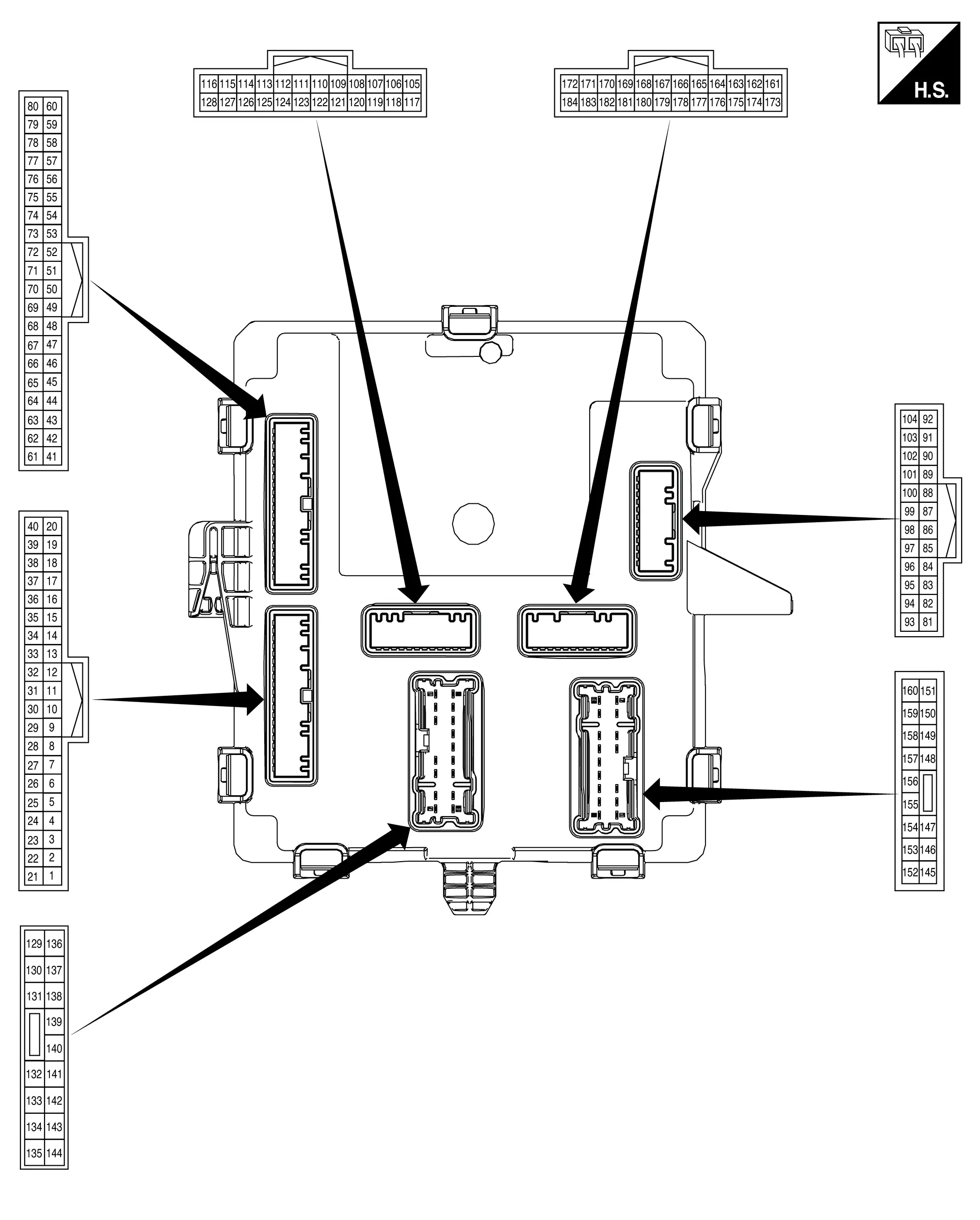
PHYSICAL VALUES
|
Terminal No. (Wire color) | Description | Condition |
Value (Approx.) | |||
|---|---|---|---|---|---|---|
| + | ŌłÆ | Signal name | Input/ Output | |||
|
11 (LG)2 (LA/LG)3 |
Ground | Drive mode select switch (2WD) ECO signal | Input | Ignition switch ON | Other than following | Battery voltage |
| Drive mode select switch (2WD) ECO position | 0 V | |||||
|
2 (SB)2 (W)3 |
Ground | Front seat belt buckle switch LH signal | Input | Ignition switch ON | Front seat belt LH is fastened | Battery voltage |
| Front seat belt LH is unfastened | 0 V | |||||
|
4 (LA/BR) |
Ground | Start/stop OFF switch signal | Input | Ignition switch ON | Start/stop OFF switch not pressed | Battery voltage |
| Start/stop OFF switch pressed | 0 V | |||||
|
18 (Y) |
Ground | Door unlock sensor signal | Input | Ignition switch ON | Front door LH LOCK status (door unlock sensor OFF) | Battery voltage |
| Front door LH UNLOCK status (door unlock sensor ON) | 0 V | |||||
|
19 (W) |
Ground | Door lock/unlock switch UNLOCK signal | Input | Ignition switch ON | Door lock/unlock switch NEUTRAL position | Battery voltage |
| Door lock/unlock switch UNLOCK position | 0 V | |||||
|
21 (LA/G) |
Ground | Luggage room lamp control | Output | Ignition switch ON | Luggage room lamp OFF (when back door is closed) | Battery voltage |
| Luggage room lamp ON (when back door is opened) | 0 V | |||||
|
28 (LA/V) |
Ground | Battery power supply | Input | Ignition switch OFF | Battery voltage | |
|
29 (Y) |
Ground | Interior room lamp relay control | Output | Interior room lamp battery saver is activated | Battery voltage | |
| Interior room lamp battery saver is not activated | 0 V | |||||
|
30 (LG) |
Ground | Accessory relay control | Output | Ignition switch OFF | Battery voltage | |
| Ignition switch ON | 0 V | |||||
|
31 (BG) |
Ground | Ignition relay-2 control | Output | Ignition switch OFF | Battery voltage | |
| Ignition switch ON | 0 V | |||||
|
33 (LA/BR)2 (G)3 |
Ground | Ignition relay-3 control | Output | Other than following | Battery voltage | |
| Engine running | 0 V | |||||
|
34 (GR) |
Ground | Power window relay control | Output | Ignition switch OFF (retained power finished) | Battery voltage | |
| Ignition switch ON | 0 V | |||||
|
35 (LA/SB) |
Ground | Rear window defogger relay control | Output | Engine running | Rear window defogger is not active | Battery voltage |
| Rear window defogger is active | 0 V | |||||
|
40 (V) |
Ground | Door lock/unlock switch LOCK signal | Input | Ignition switch ON | Door lock/unlock switch NEUTRAL position | Battery voltage |
| Door lock/unlock switch LOCK position | 0 V | |||||
|
424 (BR) |
Ground | Optical sensor ground | Output | Ignition switch ON | 0 V | |
|
474 (SB)2 (G)3 |
Ground | Optical sensor signal | Input | Ignition switch ON | When bright outside of the Nissan Ariya vehicle | 5 V |
| When dark outside of the Nissan Ariya vehicle | 0 V | |||||
|
484 (R) |
Ground | Optical sensor power supply | Output | Ignition switch ON | 5 V | |
|
49 (W) |
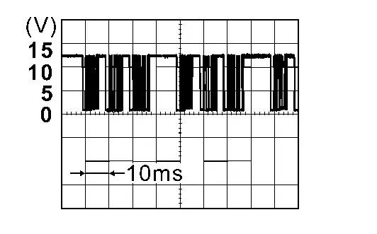
Ground | Combination switch INPUT 2 | Input | Ignition switch ON | All combination switches OFF |
|
|
50 (G) |
Ground | Combination switch INPUT 3 | Input | Ignition switch ON | All combination switches OFF |
|
|
51 (LG) |
Ground | Combination switch INPUT 5 | Input | Ignition switch ON | All combination switches OFF |
|
|
54 (L) |
Ground | Combination switch INPUT 6 | Input | Ignition switch ON | All combination switches OFF |
|
|
57 (P) |
Ground | Combination switch INPUT 4 | Input | Ignition switch ON | All combination switches OFF |
|
|
58 (R) |
Ground | Combination switch INPUT 1 | Input | Ignition switch ON | All combination switches OFF |
|
|
71 (BG) |
Ground | Combination switch OUTPUT 4 | Output | Ignition switch ON |
|
|
|
72 (GR) |
Ground | Combination switch OUTPUT 3 | Output | Ignition switch ON |
|
|
|
73 (Y) |
Ground | Combination switch OUTPUT 5 | Output | Ignition switch ON |
|
|
|
74 (V) |
Ground | Combination switch OUTPUT 6 | Output | Ignition switch ON |
|
|
|
75 (SB) |
Ground | Combination switch OUTPUT 1 | Output | Ignition switch ON |
|
|
|
76 (BR) |
Ground | Combination switch OUTPUT 2 | Output | Ignition switch ON |
|
|
|
825 (LA/L)2 (LA/GR)3 |
Ground | LIN communication (hands free sensor control unit) | Input/Output | Ignition switch ON |
|
|
|
90 (LA/G) |
Ground | Rear wiper stop position signal | Output | Ignition switch ON | Any position other than rear wiper stop position | Battery voltage |
| Rear wiper stop position | 0 V | |||||
|
91 (L)4 (GR)9 |
Ground | LIN communication (power window) | Input/output | Ignition switch ON |
|
|
|
93 (Y)2 (LA/V)6 (LA/Y)7 |
Ground | Back door opener switch signal | Input | Ignition switch ON | Back door opener switch not pressed | Battery voltage |
| Back door opener switch pressed | 0 V | |||||
|
96 (BG) |
Ground | Back door lock assembly (ajar switch) signal | Input | Ignition switch ON | Back door lock assembly (ajar switch) OFF (when back door closed) | Battery voltage |
| Back door lock assembly (ajar switch) ON (when back door opened) | 0 V | |||||
|
97 (LA/SB) |
Ground | Front door lock assembly LH (door switch) signal | Input | Ignition switch ON | Front door lock assembly LH (door switch) OFF (when door is closed) | Battery voltage |
| Front door lock assembly LH (door switch) ON (when door is opened) | 0 V | |||||
|
98 (GR) |
Ground | Front door lock assembly RH (door switch) signal | Input | Ignition switch ON | Front door lock assembly RH (door switch) OFF (when door is closed) | Battery voltage |
| Front door lock assembly RH (door switch) ON (when door is opened) | 0 V | |||||
|
99 (R) |
Ground | Rear door lock assembly LH (door switch) signal | Input | Ignition switch ON | Rear door lock assembly LH (door switch) OFF (when door is closed) | Battery voltage |
| Rear door lock assembly LH (door switch) ON (when door is opened) | 0 V | |||||
|
100 (P) |
Ground | Rear door lock assembly RH (door switch) signal | Input | Ignition switch ON | Rear door lock assembly RH (door switch) OFF (when door is closed) | Battery voltage |
| Rear door lock assembly RH (door switch) ON (when door is opened) | 0 V | |||||
|
103 (LA/R) |
Ground | CAN-Low | Input/Output | Ignition switch ON | ŌĆö | |
|
104 (LA/L) |
Ground | CAN-High | Input/Output | Ignition switch ON | ŌĆö | |
|
106 (LA/L) |
Ground | CAN-High | Input/Output | Ignition switch ON | ŌĆö | |
|
107 (LA/R) |
Ground | CAN-Low | Input/Output | Ignition switch ON | ŌĆö | |
|
115 (LG) |
Ground | Stop lamp switch 2 signal | Input | Ignition switch ON | Stop lamp switch 2 ON (brake pedal is depressed) | Battery voltage |
| Stop lamp switch 2 OFF (brake pedal is not depressed) | 0 V | |||||
|
116 (W) |
Ground | Stop lamp switch 1 signal | Input | Ignition switch ON | Stop lamp switch 1 ON (brake pedal is not depressed) | Battery voltage |
| Stop lamp switch 1 OFF (brake pedal is depressed) | 0 V | |||||
|
117 (BG) |
Ground | PTC heater relay 2 control | Output |
|
Off | Battery voltage |
| On | 0 V | |||||
|
118 (V) |
Ground | PTC heater relay 1 control | Output |
|
Off | Battery voltage |
| On | 0 V | |||||
|
121 (L) |
Ground | PTC heater relay 3 control | Output |
|
Off | Battery voltage |
| On | 0 V | |||||
|
122 (LA/Y) |
Ground | Ignition relay-1 control | Output | Ignition switch OFF | Battery voltage | |
| Ignition switch ON | 0 V | |||||
|
124 (SB)2 (R)3 |
Ground | Starter cut relay control | Output | Other than following | Battery voltage | |
| At engine cranking | 0 V | |||||
|
125 (BR) |
Ground | Back-up lamp relay control | Output | Engine running | Other than following | Battery voltage |
| Shift selector in ŌĆ£RŌĆØ position | 0 V | |||||
|
127 (G) |
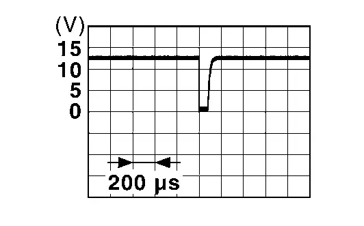
Ground | Front turn signal lamp RH power supply | Output | Ignition switch ON | Turn signal lamp RH ON |
Battery voltage (Blinking : 0 V <ŌĆō> Battery voltage) |
| Turn signal lamp RH OFF | 0 V | |||||
|
128 (P) |
Ground | Front turn signal lamp LH power supply | Output | Ignition switch ON | Turn signal lamp LH ON |
Battery voltage (Blinking : 0 V <ŌĆō> Battery voltage) |
| Turn signal lamp LH OFF | 0 V | |||||
|
131 (LA/Y) |
Ground | Map lamp control | Output | Ignition switch ON | When all doors are closed [map lamp and room lamp (door position) are turned OFF] | Battery voltage |
| Any doors opened [map lamp and room lamp (door position) are turned ON] | 0 V | |||||
|
132 (B) |
Ground | Ground | ŌĆö | Ignition switch OFF | 0 V | |
|
133 (LA/L) |
Ground | Front door RH UNLOCK control | Output | Ignition switch ON | Front door RH UNLOCK (actuator is activated) | Battery voltage |
| Other than above (actuator is not activated) | 0 V | |||||
|
134 (V) |
Ground | Front/rear door LH LOCK control | Output | Front/rear door LH LOCK (actuator is activated) | Battery voltage | |
| Other than above (actuator is not activated) | 0 V | |||||
|
135 (LA/P) |
Ground | Battery power supply (door lock 1) | Input | Ignition switch OFF | Battery voltage | |
|
136 (LA/Y) |
Ground | Battery power supply | Input | Ignition switch OFF | Battery voltage | |
|
137 (LA/W)2 (LA/L)3 |
Ground | Battery power supply (turn signal lamp) | Input | Ignition switch OFF | Battery voltage | |
|
138 (LG) |
Ground | Battery power supply (rear wiper) | Input | Ignition switch OFF | Battery voltage | |
|
140 (B) |
Ground | Ground | ŌĆö | Ignition switch OFF | 0 V | |
|
142 (LA/LG) |
Ground | Battery power supply (stop lamp) | Input | Ignition switch OFF | Battery voltage | |
|
143 (LA/G) |
Ground | Front door LH UNLOCK control | Output | Ignition switch ON | Front door LH UNLOCK (actuator is activated) | Battery voltage |
| Other than above (actuator is not activated) | 0 V | |||||
|
144 (LA/BR) |
Ground | Battery power supply (door lock 2) | Input | Ignition switch OFF | Battery voltage | |
|
14510 (V) |
Ground | Back door lock assembly control | Output | Ignition switch ON | Back door opener switch pressed (actuator is activated) | Battery voltage |
| Other than above (actuator is not activated) | 0 V | |||||
|
146 (LA/B)2 (LA/P)3 |
Ground | Map lamp control | Output | Ignition switch ON | When all doors are closed [map lamp and room lamp (door position) are turned OFF] | Battery voltage |
| Any doors opened [map lamp and room lamp (door position) are turned ON] | 0 V | |||||
|
150 (LA/BR)2 (LA/GR)3 |
Ground | Rear turn signal lamp LH power supply | Output | Ignition switch ON | Turn signal lamp LH ON |
Battery voltage (Blinking : 0 V <ŌĆō> Battery voltage) |
| Turn signal lamp LH OFF | 0 V | |||||
|
151 (LA/B) |
Ground | Mood lamp control | Output | Ignition switch ON | When all doors are closed (mood lamps are turned OFF) | Battery voltage |
| Any doors opens (mood lamps are turned ON) | 0 V | |||||
|
153 (L) |
Ground | Front/rear door RH LOCK control | Output | Ignition switch ON | Front/rear door RH LOCK (actuator is activated) | Battery voltage |
| Other than above (actuator is not activated) | 0 V | |||||
|
154 (G) |
Ground | Rear door UNLOCK control | Output | Ignition switch ON | Rear door UNLOCK (actuator is activated) | Battery voltage |
| Other than above (actuator is not activated) | 0 V | |||||
|
157 (LA/W)4 (W)9 |
Ground | Stop lamp RH power supply | Output | Ignition switch ON | Brake pedal depressed | Battery voltage |
| Brake pedal not depressed | 0 V | |||||
|
158 (LA/R) |
Ground | Rear wiper motor power supply | Output | Ignition switch ON | Rear wiper activated | Battery voltage |
| Rear wiper stopped | 0 V | |||||
|
159 (V) |
Ground | Rear turn signal lamp RH power supply | Output | Ignition switch ON | Turn signal lamp RH ON |
Battery voltage (Blinking : 0 V <ŌĆō> Battery voltage) |
| Turn signal lamp RH OFF | 0 V | |||||
|
160 (LA/Y)4 (R)9 |
Ground | Stop lamp LH and high-mounted stop lamp output | Output | Ignition switch ON | Brake pedal depressed | 9 ŌĆō 16 V |
| Brake pedal not depressed | 0 V | |||||
|
161 (LA/Y) |
Ground | Hazard switch signal | Input | Ignition switch ON | Hazard switch not pressed | Battery voltage |
| Hazard switch pressed | 0 V | |||||
|
162 (LA/L) |
Ground | CAN-High | Input/Output | Ignition switch ON | ŌĆö | |
|
163 (LA/P) |
Ground | CAN-Low | Input/Output | Ignition switch ON | ŌĆö | |
|
164 (L) |
Ground | CAN-High | Input/Output | Ignition switch ON | ŌĆö | |
|
165 (P) |
Ground | CAN-Low | Input/Output | Ignition switch ON | ŌĆö | |
|
1668 (BG)2 (LA/V)3 |
Ground | LIN communication [drive mode switch (AWD)] | Input/Output | Ignition switch ON |
|
|
|
1669 (BG)2 (LA/V)3 |
Ground | LIN communication (rain and light sensor) | Input/Output | Ignition switch ON |
|
|
|
1691 (W)2 (LA/P)3 |
Ground | Drive mode select switch (2WD) SPORT signal | Input | Ignition switch ON | Other than following | Battery voltage |
| Drive mode select switch (2WD) SPORT position | 0 V | |||||
|
178 (LA/GR) |
Ground | Side turn signal lamp RH power supply | Output | Ignition switch ON | Turn signal lamp RH ON |
Battery voltage (Blinking : 0 V <ŌĆō> Battery voltage) |
| Turn signal lamp RH OFF | 0 V | |||||
|
179 (LA/LG) |
Ground | Side turn signal lamp LH power supply | Output | Ignition switch ON | Turn signal lamp LH ON |
Battery voltage (Blinking : 0 V <ŌĆō> Battery voltage) |
| Turn signal lamp LH OFF | 0 V | |||||
|
183 (SB)2 (G)3 |
Ground | Paddle shifter SHIFT UP signal | Input | Ignition switch ON | Paddle shifter (shift up switch) not pressed | Battery voltage |
| Paddle shifter (shift up switch) pressed | 0 V | |||||
|
184 (V) |
Ground | Paddle shifter SHIFT DOWN signal | Input | Ignition switch ON | Puddle shifter (shift down switch) not pressed | Battery voltage |
| Puddle shifter (shift down switch) pressed | 0 V | |||||
 CONSULT
1: With 2WD system
2: USA production
3: Japan production
4: Without ProPILOT assist 2.1
5: With motion activated back door system
6: Japan production with ProPILOT assist 2.1
7: Japan production without ProPILOT assist 2.1
8: With all wheel drive
9: With ProPILOT assist 2.1
10: Without automatic back door
Reference Value (With Type B Meter)
TERMINAL LAYOUT
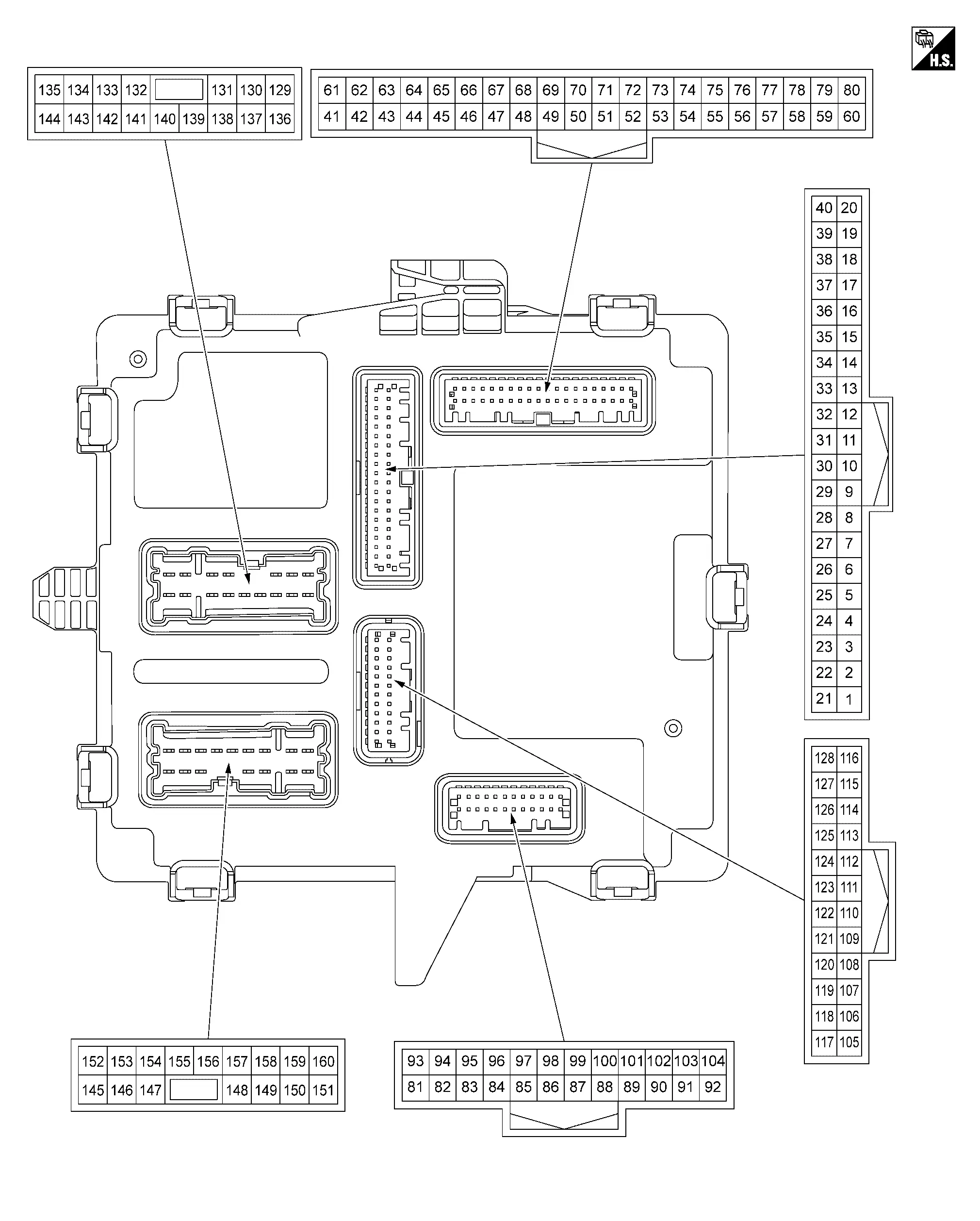
PHYSICAL VALUES
|
Terminal No. (Wire color) | Description | Condition |
Value (Approx.) | |||
|---|---|---|---|---|---|---|
| + | ŌłÆ | Signal name | Input/ Output | |||
|
11 (LA/GR) |
Ground | Side turn signal lamp RH power supply | Output | Ignition switch ON | Turn signal lamp RH ON |
Battery voltage (Blinking : 0 V <ŌĆō> Battery voltage) |
| Turn signal lamp RH OFF | 0 V | |||||
|
7 (LA/V) |
Ground | Battery power supply | Input | Ignition switch OFF | Extended storage fuse switch pushed in | Battery voltage |
| Extended storage fuse switch pulled out | 0 V | |||||
|
8 (SB)2 (G)3 |
Ground | Optical sensor signal | Input | Ignition switch ON | When bright outside of the Nissan Ariya vehicle | 5 V |
| When dark outside of the Nissan Ariya vehicle | 0 V | |||||
|
10 (Y) |
Ground | Door unlock sensor signal | Input | Ignition switch ON | Front door LH LOCK status (door unlock sensor OFF) | Battery voltage |
| Front door LH UNLOCK status (door unlock sensor ON) | 0 V | |||||
|
11 (V) |
Ground | Door lock/unlock switch LOCK signal | Input | Ignition switch ON | Door lock/unlock switch NEUTRAL position | Battery voltage |
| Door lock/unlock switch LOCK position | 0 V | |||||
|
13 (LA/Y) |
Ground | Hazard switch signal | Input | Ignition switch ON | Hazard switch not pressed | Battery voltage |
| Hazard switch pressed | 0 V | |||||
|
14 (W) |
Ground | Door lock/unlock switch UNLOCK signal | Input | Ignition switch ON | Door lock/unlock switch NEUTRAL position | Battery voltage |
| Door lock/unlock switch UNLOCK position | 0 V | |||||
|
17 (SB)2 (W)3 |
Ground | Front seat belt buckle switch LH signal | Input | Ignition switch ON | Front seat belt LH is fastened | Battery voltage |
| Front seat belt LH is unfastened | 0 V | |||||
|
20 (LA/BR) |
Ground | Start/stop OFF switch signal | Input | Ignition switch ON | Start/stop OFF switch not pressed | Battery voltage |
| Start/stop OFF switch pressed | 0 V | |||||
|
211 (LA/LG) |
Ground | Side turn signal lamp LH power supply | Output | Ignition switch ON | Turn signal lamp LH ON |
Battery voltage (Blinking : 0 V <ŌĆō> Battery voltage) |
| Turn signal lamp LH OFF | 0 V | |||||
|
24 (BR) |
Ground | LIN communication (power window) | Input/output | Ignition switch ON |
|
|
|
254 (LA/V) |
Ground | LIN communication [drive mode switch (AWD)] | Input/Output | Ignition switch ON |
|
|
|
26 (LA/L) |
Ground | CAN-High | Input/Output | Ignition switch ON | ŌĆö | |
|
27 (LA/P) |
Ground | CAN-Low | Input/Output | Ignition switch ON | ŌĆö | |
|
28 (R) |
Ground | Optical sensor power supply | Output | Ignition switch ON | 5 V | |
|
29 (BR) |
Ground | Optical sensor ground | Output | Ignition switch ON | 0 V | |
|
30 (LA/G) |
Ground | Luggage room lamp control | Output | Ignition switch ON | Luggage room lamp OFF (when back door is closed) | Battery voltage |
| Luggage room lamp ON (when back door is opened) | 0 V | |||||
|
32 (GR) |
Ground | Power window relay control | Output | Ignition switch OFF (retained power finished) | Battery voltage | |
| Ignition switch ON | 0 V | |||||
|
33 (BG) |
Ground | Ignition relay-2 control | Output | Ignition switch OFF | Battery voltage | |
| Ignition switch ON | 0 V | |||||
|
34 (LG) |
Ground | Accessory relay control | Output | Ignition switch OFF | Battery voltage | |
| Ignition switch ON | 0 V | |||||
|
37 (Y) |
Ground | Interior room lamp relay control | Output | Interior room lamp battery saver is activated | Battery voltage | |
| Interior room lamp battery saver is not activated | 0 V | |||||
|
40 (LA/BR) |
Ground | Ignition relay-3 control | Output | Other than following | Battery voltage | |
| Engine running | 0 V | |||||
|
45 (L) |
Ground | CAN-High | Input/Output | Ignition switch ON | ŌĆö | |
|
46 (P) |
Ground | CAN-Low | Input/Output | Ignition switch ON | ŌĆö | |
|
48 (SB) |
Ground | Combination switch OUTPUT 1 | Output | Ignition switch ON |
|
|
|
49 (BR) |
Ground | Combination switch OUTPUT 2 | Output | Ignition switch ON |
|
|
|
50 (Y) |
Ground | Combination switch OUTPUT 5 | Output | Ignition switch ON |
|
|
|
51 (V) |
Ground | Combination switch OUTPUT 6 | Output | Ignition switch ON |
|
|
|
52 (BG) |
Ground | Combination switch OUTPUT 4 | Output | Ignition switch ON |
|
|
|
53 (GR) |
Ground | Combination switch OUTPUT 3 | Output | Ignition switch ON |
|
|
|
575 (W) |
Ground | Drive mode select switch (AWD) SPORT signal | Input | Ignition switch ON | Other than following | Battery voltage |
| Drive mode select switch (AWD) SPORT position | 0 V | |||||
|
63 (LA/SB) |
Ground | Rear window defogger relay control | Output | Engine running | Rear window defogger is not active | Battery voltage |
| Rear window defogger is active | 0 V | |||||
|
67 (R) |
Ground | Combination switch INPUT 1 | Input | Ignition switch ON | All combination switches OFF |
|
|
68 (W) |
Ground | Combination switch INPUT 2 | Input | Ignition switch ON | All combination switches OFF |
|
|
69 (G) |
Ground | Combination switch INPUT 3 | Input | Ignition switch ON | All combination switches OFF |
|
|
70 (P) |
Ground | Combination switch INPUT 4 | Input | Ignition switch ON | All combination switches OFF |
|
|
71 (LG) |
Ground | Combination switch INPUT 5 | Input | Ignition switch ON | All combination switches OFF |
|
|
72 (L) |
Ground | Combination switch INPUT 6 | Input | Ignition switch ON | All combination switches OFF |
|
|
78 (SB)2 (G)3 |
Ground | Paddle shifter SHIFT UP signal | Input | Ignition switch ON | Paddle shifter (shift up switch) not pressed | Battery voltage |
| Paddle shifter (shift up switch) pressed | 0 V | |||||
|
79 (V) |
Ground | Paddle shifter SHIFT DOWN signal | Input | Ignition switch ON | Puddle shifter (shift down switch) not pressed | Battery voltage |
| Puddle shifter (shift down switch) pressed | 0 V | |||||
|
805 (LG) |
Ground | Drive mode switch (2WD) ECO signal | Input | Ignition switch ON | Other than following | Battery voltage |
| Drive mode switch (2WD) ECO position | 0 V | |||||
|
81 (LA/SB) |
Ground | Front door lock assembly LH (door switch) signal | Input | Ignition switch ON | Front door lock assembly LH (door switch) OFF (when door is closed) | Battery voltage |
| Front door lock assembly LH (door switch) ON (when door is opened) | 0 V | |||||
|
836 (LA/L)2 (LA/GR)3 |
Ground | LIN communication (hands free sensor control unit) | Input/Output | Ignition switch ON |
|
|
|
86 (LA/R) |
Ground | CAN-Low | Input/Output | Ignition switch ON | ŌĆö | |
|
87 (LA/L) |
Ground | CAN-High | Input/Output | Ignition switch ON | ŌĆö | |
|
93 (GR) |
Ground | Front door lock assembly RH (door switch) signal | Input | Ignition switch ON | Front door lock assembly RH (door switch) OFF (when door is closed) | Battery voltage |
| Front door lock assembly RH (door switch) ON (when door is opened) | 0 V | |||||
|
94 (R) |
Ground | Rear door lock assembly LH (door switch) signal | Input | Ignition switch ON | Rear door lock assembly LH (door switch) OFF (when door is closed) | Battery voltage |
| Rear door lock assembly LH (door switch) ON (when door is opened) | 0 V | |||||
|
95 (P) |
Ground | Rear door lock assembly RH (door switch) signal | Input | Ignition switch ON | Rear door lock assembly RH (door switch) OFF (when door is closed) | Battery voltage |
| Rear door lock assembly RH (door switch) ON (when door is opened) | 0 V | |||||
|
96 (BG) |
Ground | Back door lock assembly (ajar switch) signal | Input | Ignition switch ON | Back door lock assembly (ajar switch) OFF (when back door closed) | Battery voltage |
| Back door lock assembly (ajar switch) ON (when back door opened) | 0 V | |||||
|
98 (Y) |
Ground | Back door opener switch signal | Input | Ignition switch ON | Back door opener switch not pressed | Battery voltage |
| Back door opener switch pressed | 0 V | |||||
|
103 (LA/G) |
Ground | Rear wiper stop position signal | Output | Ignition switch ON | Any position other than rear wiper stop position | Battery voltage |
| Rear wiper stop position | 0 V | |||||
|
105 (LA/Y) |
Ground | Ignition relay-1 control | Output | Ignition switch OFF | Battery voltage | |
| Ignition switch ON | 0 V | |||||
|
110 (LG) |
Ground | Stop lamp switch 2 signal | Input | Ignition switch ON | Stop lamp switch 2 ON (brake pedal is depressed) | Battery voltage |
| Stop lamp switch 2 OFF (brake pedal is not depressed) | 0 V | |||||
|
111 (W) |
Ground | Stop lamp switch 1 signal | Input | Ignition switch ON | Stop lamp switch 1 ON (brake pedal is not depressed) | Battery voltage |
| Stop lamp switch 1 OFF (brake pedal is depressed) | 0 V | |||||
|
116 (G) |
Ground | Front turn signal lamp RH power supply | Output | Ignition switch ON | Turn signal lamp RH ON |
Battery voltage (Blinking : 0 V <ŌĆō> Battery voltage) |
| Turn signal lamp RH OFF | 0 V | |||||
|
117 (LA/R) |
Ground | CAN-Low | Input/Output | Ignition switch ON | ŌĆö | |
|
118 (LA/L) |
Ground | CAN-High | Input/Output | Ignition switch ON | ŌĆö | |
|
119 (BR) |
Ground | Back-up lamp relay control | Output | Engine running | Other than following | Battery voltage |
| Shift selector in ŌĆ£RŌĆØ position | 0 V | |||||
|
123 (SB)2 (R)3 |
Ground | Starter cut relay control | Output | Other than following | Battery voltage | |
| At engine cranking | 0 V | |||||
|
125 (V) |
Ground | PTC heater relay 1 control | Output |
|
Off | Battery voltage |
| On | 0 V | |||||
|
126 (L) |
Ground | PTC heater relay 3 control | Output |
|
Off | Battery voltage |
| On | 0 V | |||||
|
127 (BG) |
Ground | PTC heater relay 2 control | Output |
|
Off | Battery voltage |
| On | 0 V | |||||
|
128 (P) |
Ground | Front turn signal lamp LH power supply | Output | Ignition switch ON | Turn signal lamp LH ON |
Battery voltage (Blinking : 0 V <ŌĆō> Battery voltage) |
| Turn signal lamp LH OFF | 0 V | |||||
|
129 (B) |
Ground | Ground | ŌĆö | Ignition switch OFF | 0 V | |
|
130 (LA/Y) |
Ground | Map lamp control | Output | Ignition switch ON | When all doors are closed [map lamp and room lamp (door position) are turned OFF] | Battery voltage |
| Any doors opened [map lamp and room lamp (door position) are turned ON] | 0 V | |||||
|
132 (LA/L) |
Ground | Front door RH UNLOCK control | Output | Ignition switch ON | Front door RH UNLOCK (actuator is activated) | Battery voltage |
| Other than above (actuator is not activated) | 0 V | |||||
|
133 (LA/Y) |
Ground | Battery power supply | Input | Ignition switch OFF | Battery voltage | |
|
134 (LA/G) |
Ground | Front door LH UNLOCK control | Output | Ignition switch ON | Front door LH UNLOCK (actuator is activated) | Battery voltage |
| Other than above (actuator is not activated) | 0 V | |||||
|
135 (LA/P) |
Ground | Battery power supply (front door lock) | Input | Ignition switch OFF | Battery voltage | |
|
136 (LA/W)2 (LA/L)3 |
Ground | Battery power supply (turn signal lamp) | Input | Ignition switch OFF | Battery voltage | |
|
137 (B) |
Ground | Ground | ŌĆö | Ignition switch OFF | 0 V | |
|
138 (LG) |
Ground | Battery power supply (rear wiper) | Input | Ignition switch OFF | Battery voltage | |
|
139 (LA/LG) |
Ground | Battery power supply (stop lamp) | Input | Ignition switch OFF | Battery voltage | |
|
142 (V) |
Ground | Front/rear door LH LOCK control | Output | Front/rear door LH LOCK (actuator is activated) | Battery voltage | |
| Other than above (actuator is not activated) | 0 V | |||||
|
144 (LA/BR) |
Ground | Battery power supply (rear door lock) | Input | Ignition switch OFF | Battery voltage | |
|
1457 (V) |
Ground | Back door lock assembly control | Output | Ignition switch ON | Back door opener switch pressed (actuator is activated) | Battery voltage |
| Other than above (actuator is not activated) | 0 V | |||||
|
147 (LA/B)2 (LA/GR)3 |
Ground | Map lamp control | Output | Ignition switch ON | When all doors are closed [map lamp and room lamp (door position) are turned OFF] | Battery voltage |
| Any doors opened [map lamp and room lamp (door position) are turned ON] | 0 V | |||||
|
148 (LA/R) |
Ground | Rear wiper motor power supply | Output | Ignition switch ON | Rear wiper activated | Battery voltage |
| Rear wiper stopped | 0 V | |||||
|
150 (LA/B) |
Ground | Mood lamp control | Output | Ignition switch ON | When all doors are closed (mood lamps are turned OFF) | Battery voltage |
| Any doors opens (mood lamps are turned ON) | 0 V | |||||
|
151 (LA/BR)2 (LA/GR)3 |
Ground | Rear turn signal lamp LH power supply | Output | Ignition switch ON | Turn signal lamp LH ON |
Battery voltage (Blinking : 0 V <ŌĆō> Battery voltage) |
| Turn signal lamp LH OFF | 0 V | |||||
|
154 (L) |
Ground | Front/rear door RH LOCK control | Output | Ignition switch ON | Front/rear door RH LOCK (actuator is activated) | Battery voltage |
| Other than above (actuator is not activated) | 0 V | |||||
|
155 (G) |
Ground | Rear door UNLOCK control | Output | Ignition switch ON | Rear door UNLOCK (actuator is activated) | Battery voltage |
| Other than above (actuator is not activated) | 0 V | |||||
|
157 (W) |
Ground | Stop lamp RH power supply | Output | Ignition switch ON | Brake pedal depressed | Battery voltage |
| Brake pedal not depressed | 0 V | |||||
|
159 (V) |
Ground | Rear turn signal lamp RH power supply | Output | Ignition switch ON | Turn signal lamp RH ON |
Battery voltage (Blinking : 0 V <ŌĆō> Battery voltage) |
| Turn signal lamp RH OFF | 0 V | |||||
|
160 (LA/Y) |
Ground | Stop lamp LH and high-mounted stop lamp output | Output | Ignition switch ON | Brake pedal depressed | Battery voltage |
| Brake pedal not depressed | 0 V | |||||
1: With side turn signal lamps
2: USA production
3: Japan production
4: With all wheel drive
5: With 2WD system
6: With motion activated back door system
7: Without automatic back door
Fail-safe
FAIL-SAFE CONTROL BY DTC
BCM performs fail-safe control when any DTC are detected.
| Display contents of CONSULT | Fail-safe |
|---|---|
| B2C95-01: Combination switch | Turns ON the headlamp (LO) |
| B2C95-64: Combination switch | Turns ON the headlamp (LO) |
| B2C96-49: Light sensor | Turns ON the headlamp (LO) |
| B2CB4-49: Rain sensor |
|
| B2CB5-64: Rear wiper | Stop rear wiper power supply for 1min |
| B2FAE-12: Ignition relay-1 | Inhibit engine cranking |
| B2FAE-14: Ignition relay-1 | Inhibit engine cranking |
DTC Inspection Priority Chart
If some DTCs are displayed at the same time, perform inspections one by one based on the following priority chart:
| Priority | DTC |
|---|---|
| 1 |
|
| 2 | U1327ŌĆō52: MAC key update |
| 3 |
|
| 4 |
|
| 5 |
|
| 6 |
|
| 7 |
|
DTC Index
NOTE:
The details of time display are as follows:
-
CRNT: A malfunction is detected now
-
PAST: A malfunction was detected in the past
├Ś:Applicable
| CONSULT display | Fail-safe | Freeze Frame Data | Reference |
|---|---|---|---|
| B2556-73: PUSH-BTN IGN SW | ŌĆö | ├Ś | DTC Description |
| B2C20-12: Starter control relay | ŌĆö | ŌĆö | DTC Description |
| B2C20-14: Starter control relay | ŌĆö | ŌĆö | DTC Description |
| B2C20-23: Starter control relay | ŌĆö | ŌĆö | DTC Description |
| B2C20-24: Starter control relay | ŌĆö | ŌĆö | DTC Description |
| B2C40-04: Power window main switch | ŌĆö | ŌĆö | DTC Description |
| B2C40-95: Power window main switch | ŌĆö | ŌĆö | DTC Description |
| B2C41-04: Power window motor FL | ŌĆö | ŌĆö | DTC Description |
| B2C41-95: Power window motor FL | ŌĆö | ŌĆö | DTC Description |
| B2C95-01: Combination switch | ├Ś | ŌĆö | DTC Description |
| B2C95-64: Combination switch | ├Ś | ŌĆö | DTC Description |
| B2C96-49: Light sensor | ├Ś | ŌĆö | DTC Description |
| B2CB4-49: Rain sensor | ├Ś | ŌĆö | DTC Description |
| B2CB5-64: Rear wiper | ├Ś | ŌĆö | DTC Description |
| B2CCF-04: Passenger door mirror control module | ŌĆö | ŌĆö | DTC Description |
| B2F06-11: Back door/trunk opener switch | ŌĆö | ŌĆö | DTC Description |
| B2F06-15: Back door/trunk opener switch | ŌĆö | ŌĆö | DTC Description |
| B2F60-55: Seat belt buckle switch (driver side) | ŌĆö | ŌĆö | DTC Description |
| B2F70-01: Stop lamp | ŌĆö | ŌĆö | DTC Description |
| B2F70-02: Stop lamp | ŌĆö | ŌĆö | DTC Description |
| B2F71-23: Stop lamp | ŌĆö | ŌĆö | DTC Description |
| B2F71-24: Stop lamp | ŌĆö | ŌĆö | DTC Description |
| B2F72-23: Stop lamp | ŌĆö | ŌĆö | DTC Description |
| B2F72-24: Stop lamp | ŌĆö | ŌĆö | DTC Description |
| B2F98-04: Sunshade motor | ŌĆö | ŌĆö | DTC Description |
| B2F99-04: Sunroof motor | ŌĆö | ŌĆö | DTC Description |
| B2FAC-12: Accessory relay | ŌĆö | ŌĆö | DTC Description |
| B2FAC-14: Accessory relay | ŌĆö | ŌĆö | DTC Description |
| B2FAE-12: Ignition relay-1 | ├Ś | ŌĆö | DTC Description |
| B2FAE-14: Ignition relay-1 | ├Ś | ŌĆö | DTC Description |
| B2FAF-12: Ignition relay-2 | ŌĆö | ŌĆö | DTC Description |
| B2FAF-14: Ignition relay-2 | ŌĆö | ŌĆö | DTC Description |
| B2FB0-12: Ignition relay-3 | ŌĆö | ŌĆö | DTC Description |
| B2FB0-14: Ignition relay-3 | ŌĆö | ŌĆö | DTC Description |
| C1700-54: Control unit | ŌĆö | ŌĆö | DTC Description |
| C1700-55: Control unit | ŌĆö | ŌĆö | DTC Description |
| C1700-86: Control unit | ŌĆö | ŌĆö | DTC Description |
| C1711-7B: Low tire pressure FL | ŌĆö | ├Ś | DTC Description |
| C1712-7B: Low tire pressure FR | ŌĆö | ├Ś | DTC Description |
| C1713-7B: Low tire pressure RR | ŌĆö | ├Ś | DTC Description |
| C1714-7B: Low tire pressure RL | ŌĆö | ├Ś | DTC Description |
| C1731-16: Tire pressure sensor FL | ŌĆö | ├Ś | DTC Description |
| C1731-68: Tire pressure sensor FL | ŌĆö | ├Ś | DTC Description |
| C1732-16: Tire pressure sensor FR | ŌĆö | ├Ś | DTC Description |
| C1732-68: Tire pressure sensor FR | ŌĆö | ├Ś | DTC Description |
| C1733-16: Tire pressure sensor RR | ŌĆö | ├Ś | DTC Description |
| C1733-68: Tire pressure sensor RR | ŌĆö | ├Ś | DTC Description |
| C1734-16: Tire pressure sensor RL | ŌĆö | ├Ś | DTC Description |
| C1734-68: Tire pressure sensor RL | ŌĆö | ├Ś | DTC Description |
| C1741-21: Tire pressure sensor no data FL | ŌĆö | ├Ś | DTC Description |
| C1742-21: Tire pressure sensor no data FR | ŌĆö | ├Ś | DTC Description |
| C1743-21: Tire pressure sensor no data RR | ŌĆö | ├Ś | DTC Description |
| C1744-21: Tire pressure sensor no data RL | ŌĆö | ├Ś | DTC Description |
| U1327-52: MAC key update | ŌĆö | ŌĆö | DTC Description |
| U1327-54: MAC key update | ŌĆö | ŌĆö | DTC Description |
| U1C01-08: LIN communication | ŌĆö | ├Ś | DTC Description |
| U1C02-08: LIN communication | ŌĆö | ├Ś | DTC Description |
| U2140-57: CAN comm err (ECM) | ŌĆö | ŌĆö | DTC Description |
| U2152-57: CAN comm err (ADAS control unit) | ŌĆö | ŌĆö | DTC Description |
| U2175-57: CAN comm err (AVM) | ŌĆö | ŌĆö | DTC Description |
| U2176-57: CAN comm err (CCM/ST angle sensor) | ŌĆö | ŌĆö | DTC Description |
| U3D00-06: Cell voltage circuit | ŌĆö | ŌĆö | DTC Description |
| U3D01-51: FOTA | ŌĆö | ŌĆö | DTC Description |
├Ś:Applicable
| CONSULT display | Fail-safe | Freeze Frame Data | Reference |
|---|---|---|---|
| U0073-00: Control module comm Bus A Off | ŌĆö | ŌĆö | DTC Description |
| U0075-00: Control module comm Bus C Off | ŌĆö | ŌĆö | DTC Description |
| U20C5-87: CAN comm err (audio amp.) | ŌĆö | ŌĆö | DTC Description |
| U2140-87: CAN comm err (ECM) | ŌĆö | ŌĆö | DTC Description |
| U2141-87: CAN comm err (TCM) | ŌĆö | ŌĆö | DTC Description |
| U2148-87: CAN comm err (brake control unit) | ŌĆö | ŌĆö | DTC Description |
| U2152-87: CAN comm err (ADAS control unit) | ŌĆö | ŌĆö | DTC Description |
| U2154-87: CAN comm err (MIU) | ŌĆö | ŌĆö | DTC Description |
| U216B-87: CAN comm err (front camera) | ŌĆö | ŌĆö | DTC Description |
| U2175-87: CAN comm err (AVM) | ŌĆö | ŌĆö | DTC Description |
| U2176-87: CAN comm err (CCM/ST angle sensor) | ŌĆö | ŌĆö | DTC Description |
| U2218-87: CAN comm err (Intelligent Key) | ŌĆö | ŌĆö | DTC Description |
| U2250-87: CAN comm err (AIR BAG) | ŌĆö | ŌĆö | DTC Description |
| U2253-87: CAN comm err (HVAC) | ŌĆö | ŌĆö | DTC Description |
| U225B-87: CAN comm err (IPDM E/R) | ŌĆö | ŌĆö | DTC Description |
| U2314-87: CAN comm err (ANC) | ŌĆö | ŌĆö | DTC Description |
| U234E-87: CAN comm err (combination meter) | ŌĆö | ŌĆö | DTC Description |
| U2369-87: CAN comm err (PSD/MHB) | ŌĆö | ŌĆö | DTC Description |
| U237C-87: CAN comm err (seat) | ŌĆö | ŌĆö | DTC Description |
| U2A06-88: Comm Bus Off V-FD | ŌĆö | ŌĆö | DTC Description |
Other materials:
Its Can Communication 1 Circuit
Diagnosis Procedure
CHECK NETWORK DIAGNOSIS
Check the "Network diagnosis" results from CONSULT to see that the diagnostic CAN communication circuit have no malfunction.
Are the diagnostic CAN communication circuit normal?
YES>>
GO TO 2.
NO>>
Check and repair diagnostic CAN commu ...
Drivetrain Can Communication 2 Circuit
Diagnosis Procedure
CHECK NETWORK DIAGNOSIS
Check the "Network diagnosis" results from CONSULT to see that the diagnostic CAN communication circuit have no malfunction.
Are the diagnostic CAN communication circuit normal?
YES>>
GO TO 2.
NO>>
Check and repair diagnostic CAN commu ...
System
I-Fcw
System Description
SYSTEM DIAGRAM Component Description
ABS actuator and electric unit (control unit)
ABS Actuator and Electric Unit (Control Unit)
Combination meter (FULL TFT METER)
Combination Meter
Combination meter (7 INCH INFORMATION DISPLAY)
Combination Meter
...