Nissan Rogue (T33) 2021-Present Service Manual: Dtc/circuit Diagnosis :: Reclining Sensor
Component Function Check
CHECK FUNCTION
 CONSULT
-
Ignition switch ON.
-
Select “Reclining motor position” in “Data monitor” mode of “DRIVER SEAT”.
-
Check reclining sensor signal under the following conditions.
| Monitor item | Condition | Status | |
|---|---|---|---|
| Reclining motor position | Seat reclining | Operate (forward) | Change (increase) |
| Operate (backward) | Change (decrease) | ||
| Other than the above | No change | ||
Is the inspection result normal?
YES>>Inspection End.
NO>>Refer to Diagnosis Procedure.
Diagnosis Procedure
CHECK RECLINING SENSOR SIGNAL
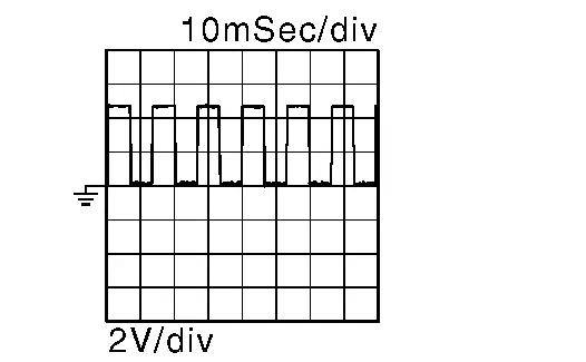
Check signal between driver seat control unit harness connector and ground with oscilloscope.
| (+) | (-) | Condition |
Signal (Reference value) | ||
|---|---|---|---|---|---|
| Driver seat control unit | |||||
| Connector | Terminal | ||||
| B213 | 36 | Ground | Seat reclining | Operate |
|
| Other than the above | 5 V* | ||||
*: When the power consumption control of driver seat control unit is in wake-up state.
Is the inspection result normal?
YES>>Replace driver seat control unit. Refer to Removal and Installation.
NO>>GO TO 2.
CHECK RECLINING SENSOR SIGNAL CIRCUIT (OPEN)
-
Ignition switch OFF.
-
Disconnect driver seat control unit connector and reclining motor LH connector.
-
Check continuity between driver seat control unit harness connector and reclining motor LH harness connector.
Driver seat control unit Reclining motor LH Continuity Connector Terminal Connector Terminal B213 36 B217 5 Yes
Is the inspection result normal?
YES>>GO TO 3.
NO>>Repair the harness or connector.
CHECK RECLINING SENSOR SIGNAL CIRCUIT (SHORT TO GROUND)
Check continuity between driver seat control unit harness connector and ground.
| Driver seat control unit | (—) | Continuity | |
|---|---|---|---|
| Connector | Terminal | ||
| B213 | 36 | Ground | No |
Is the inspection result normal?
YES>>GO TO 4.
NO>>Repair the harness or connector.
CHECK RECLINING SENSOR POWER SUPPLY VOLTAGE
-
Connect driver seat control unit connector.
-
Check voltage between reclining motor LH harness connector and ground.
(+) (-) Voltage
(Approx.)Reclining motor LH Connector Terminal B217 2 Ground Battery voltage
Is the inspection result normal?
YES>>GO TO 7.
NO>>GO TO 5.
CHECK RECLINING SENSOR POWER SUPPLY CIRCUIT (OPEN)
-
Disconnect driver seat control unit connector.
-
Check continuity between reclining motor LH harness connector and driver seat control unit harness connector.
Reclining motor LH Driver seat control unit Continuity Connector Terminal Connector Terminal B217 2 B213 34 Yes
Is the inspection result normal?
YES>>GO TO 6.
NO>>Repair the harness or connector.
CHECK RECLINING SENSOR POWER SUPPLY CIRCUIT (SHORT TO GROUND)
Check continuity between reclining motor LH harness connector and ground.
| Reclining motor LH | (—) | Continuity | |
|---|---|---|---|
| Connector | Terminal | ||
| B217 | 2 | Ground | No |
Is the inspection result normal?
YES>>Replace driver seat control unit. Refer to Removal and Installation.
NO>>Repair the harness or connector.
CHECK RECLINING SENSOR GROUND CIRCUIT (OPEN)
-
Disconnect driver seat control unit connector.
-
Check continuity between reclining motor LH harness connector and driver seat control unit harness connector.
Reclining motor LH Driver seat control unit Continuity Connector Terminal Connector Terminal B217 4 B213 33 Yes
Is the inspection result normal?
YES>>Replace seat back frame. Refer toDisassembly and Assembly.
NO>>Repair the harness or connector.
Other materials:
P050a Cold Start Control
DTC Description
DESCRIPTIONECM controls ignition timing and engine idle speed when engine is started with pre-warming up condition.This control promotes the activation of three way catalyst by heating the catalyst and reduces emissions.DTC DETECTION LOGIC DTC
CONSULT screen terms
(Trouble diag ...
With Idle Start/stop. Removal and Installation. Sub Starter & Generator
Sub Starter & Generator
Exploded View
REMOVAL 1.
Collar
2.
Sub starter, generator and compressor bracket
3.
Sub starter & generator
4.
Sub starter & generator harness connector
5.
“B” terminal
-
-
: Nissan Ariya Vehicle front
, , , : In ...
Rear Final Drive: R145. Preparation. Preparation
Preparation
Special Service Tools
The actual shapes of TechMate tools may differ from those of special service tools illustrated here.
Tool number
(TechMate No.)
Tool name Description
KV40100610
(NI-26089)
Drift
a: 63 mm (2.48 in) dia.
b: 54.3 mm (2.138 in) dia.
Removing ...