Nissan Rogue (T33) 2021-Present Service Manual: Dtc/circuit Diagnosis :: Passenger Door Mirror Control Module
Diagnosis Procedure
CHECK FUSE
-
Ignition switch OFF.
-
Check that the following fuse is not blown (open):
Unit Location Fuse No. Capacity Passenger door mirror control module Fuse block (J/B) 45 5 A
Is the fuse blown (open) ?
YES>>Replace the blown (open) fuse after repairing the affected circuit if a fuse is blown (open).
NO>>GO TO 2.
CHECK PASSENGER DOOR MIRROR CONTROL MODULE POWER SUPPLY
-
Disconnect passenger door mirror control module connector.
-
Ignition switch ON.
-
Check voltage between passenger door mirror control module harness connector and ground.
(+) (ŌłÆ) Voltage
(Approx.)Passenger door mirror control module Connector Terminal D108 4 Ground Battery voltage
Is the inspection result normal?
YES>>GO TO 3.
NO>>Repair or replace harness and check fuse.
CHECK LIN COMMUNICATION SIGNAL
-
Ignition switch OFF.
-
Connect passenger door mirror control module connector.
-
Ignition switch ON.
-
Check signal between passenger door mirror control module harness connector and ground using an oscilloscope.
(+) (ŌłÆ) Signal
(Reference value)Passenger door mirror control module Connector Terminal D108 7 Ground 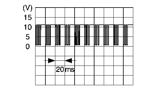
Is the inspection result normal?
YES>>GO TO 4.
NO>>Repair or replace harness.
CHECK PASSENGER DOOR MIRROR CONTROL MODULE CIRCUIT
-
Ignition switch OFF.
-
Disconnect passenger door mirror control module and door mirror RH connector.
-
Check continuity between passenger door mirror control module harness connector and door mirror RH harness connector.
Passenger door mirror control module Door mirror RH Continuity Connector Terminal Connector Terminal D108 1 D106 13 Yes 2 5 3 10 5 14 6 6 10 2 11 3 -
Check continuity between passenger door mirror control module harness connector and ground.
Passenger door mirror control module ŌĆö Continuity Connector Terminal D108 1 Ground No 2 3 5 6 10 11
Is the inspection result normal?
YES>>GO TO 5.
NO>>Repair or replace harness.
CHECK PASSENGER DOOR MIRROR CONTROL MODULE GROUND CIRCUIT
Check continuity between passenger door mirror control module harness connector and ground.
| Passenger door mirror control module | ŌĆö | Continuity | ||
|---|---|---|---|---|
| Connector | Terminal | |||
| D108 | 12 | Ground | Yes | |
Is the inspection result normal?
YES>>GO TO 6.
NO>>Repair or replace harness.
REPLACE DOOR MIRROR RH
Replace door mirror RH. Refer to Removal and Installation.
Is the inspection result normal?
YES>>Inspection End.
NO>>GO TO 7.
REPLACE PASSENGER DOOR MIRROR CONTROL MODULE
Replace passenger door mirror control module. Refer to Removal and Installation.
Is the inspection result normal?
YES>>Inspection End.
NO>>GO TO 8.
REPLACE BCM
Replace BCM. Refer to Removal and Installation.
Is the inspection result normal?
YES>>Inspection End.
NO>>GO TO 9.
CHECK INTERMITTENT INCIDENT
Check intermittent incident. Refer to Intermittent Incident.
>>
Inspection End.
Other materials:
Removal and Installation. Rear Door
Exploded View
Rear door panel
Grommet
Rear door striker
TORX bolt
Rear door check link
Rear door hinge (lower)
Rear door hinge (upper)
Rear door weather-strip
Double-sided tape [t: 1.2 mm (0.047 in)]
Double-sided tape [t: 0.8 mm (0.031 in)]
&n ...
Hood
WARNING
Make sure the hood of your Nissan Rogue is fully closed and latched before driving.
Do not open the hood if steam or smoke is coming from the engine compartment.
1. Pull the hood lock release handle 1 located below the driverŌĆÖs side instrument panel
to slightly raise the hood of t ...
Information Display (combination Meter)
Remote Engine Start Information
DESIGN/PURPOSEInformation display informs the driver that the engine can be started. Symbol Message
Push brake and start switch to drive
SYNCHRONIZATION WITH MASTER WARNING LAMPNo applicableSYSTEM DIAGRAMSIGNAL PATH
BCM transmits meter display signal ...