Nissan Rogue (T33) 2021-Present Service Manual: Dtc/circuit Diagnosis :: B2422-78 Back Door Position Abnormal
DTC Description
DTC DETECTION LOGIC
| DTC No. |
CONSULT screen items (Trouble diagnosis content) | DTC Detection Condition | |
|---|---|---|---|
| B2422-78 |
Back door position abnormal (Back door position abnormal) |
Diagnosis condition | All times |
| Signal (terminal) | Encoder LH signal | ||
| Threshold | When the automatic back door control unit detects back door position malfunction according to the encoder signal | ||
| Diagnosis delay time | 1 second or less | ||
POSSIBLE CAUSE
-
Spindle unit LH
-
Automatic back door control unit
-
Harness or connector (encoder LH circuit is open or shorted)
FAIL-SAFE
Inhibit automatic back door system (only operate back door closure function)
DTC CONFIRMATION PROCEDURE
DTC CONFIRMATION
 CONSULT
-
Ignition switch ON.
-
Select “Self diagnosis result” mode of “AUTOMATIC BACK DOOR”.
Is DTC detected?
YES>>Refer to DTC Diagnosis Procedure.
NO-1>>To check malfunction symptom before repair: Refer to Intermittent Incident.
NO-2>>Confirmation after repair: Inspection End.
DTC Diagnosis Procedure
CHECK ENCODER SIGNAL
CONSULT
-
Ignition switch ON.
-
Select “Spindle sensor LH” in “Data monitor” mode of "AUTOMATIC BACK DOOR".
-
Check that the function operates normally according to the following conditions.
Monitor item Condition Status Spindle sensor LH Back door Open The numeral value increases Close The numeral value decreases
Is the inspection result normal?
YES>>Check intermittent incident. Refer to Intermittent Incident.
NO>>GO TO 2.
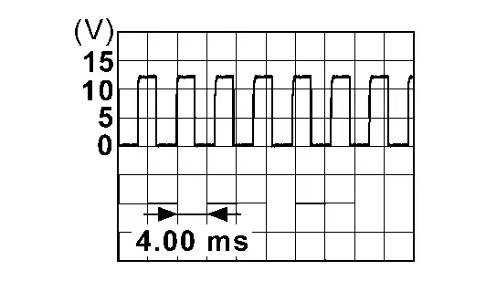
CHECK ENCODER INPUT SIGNAL
Check signal between automatic back door control unit harness connector and ground using oscilloscope.
| (+) | (–) | Condition |
Signal (Reference value) (Approx.) | ||
|---|---|---|---|---|---|
| Automatic back door control unit | |||||
| Connector | Terminal | ||||
| B55 | 29 | Ground | Back door | Moving (auto) |
|
| When stopped | 0 V or Battery voltage | ||||
| 30 | Moving (auto) |
|
|||
| When stopped | 0 V or Battery voltage | ||||
Is the inspection result normal?
YES>>GO TO 3.
NO>>GO TO 6.
CHECK CONNECTOR
-
Ignition switch OFF.
-
Check the automatic back door control unit harness connector for disconnection or looseness.
-
Check the touch sensor RH harness connector for disconnection or looseness.
Is the inspection result normal?
YES>>GO TO 4.
NO>>Repair/replace harness or connector, securely lock the connector, and GO TO 6.
CHECK AUTOMATIC BACK DOOR CONTROL UNIT POWER SUPPLY AND GROUND CIRCUIT
Check the automatic back door control unit power supply and ground circuits. Refer to Diagnosis Procedure.
Is the inspection result normal?
YES>>GO TO 5.
NO>>Repair/replace harness, connector, fuse, or fusible link, and GO TO 5.
CHECK TERMINAL
-
Ignition switch OFF.
-
Disconnect automatic back door control unit harness connector and then check the automatic back door control unit pin terminals for damage or loose connection with harness connector.
-
Disconnect touch sensor RH harness connector and check touch sensor RH pin terminal for damage or loose connection with harness connector.
Is the inspection result normal?
YES>>Replace automatic back door control unit. Refer to Removal and Installation.
NO>>Repair/replace harness, connector, or terminal.
CHECK ENCODER CIRCUIT
-
Disconnect automatic back door control unit connector and spindle unit LH connector.
-
Check continuity between automatic back door control unit harness connector and spindle unit LH harness connector.
Automatic back door control unit Spindle unit LH Continuity Connector Terminal Connector Terminal B55 29 B95 5 Yes 30 3 -
Check continuity between automatic back door control unit harness connector and ground.
Automatic back door control unit — Continuity Connector Terminal B55 29 Ground No 30
Is the inspection result normal?
YES>>Replace spindle unit LH. Refer to Removal and Installation.
NO>>Repair or replace harness.
Other materials:
Security systems
Basic information
Your vehicle includes two types of security systems designed to help protect the Nissan Rogue from unauthorized access:
Vehicle security system (if so equipped)
NISSAN Vehicle Immobilizer System
Vehicle Security System
Basic information
The vehicle security system activates ...
Dtc/circuit Diagnosis. U3d00-06 Cell Voltage Circuit
DTC Description
DTC DETECTION LOGIC DTC No.
CONSULT screen items
(Trouble diagnosis content) DTC Detection Condition
U3D00-06
Cell voltage circuit
(Cell voltage circuit)
Diagnosis condition
Ignition switch is ON.
Signal (terminal)
BCM (CPU).
Threshold
When a CPU fu ...
Removal and Installation. Driver Seat Control Unit
Removal and Installation
REMOVALRemove driver seat. Refer to Removal and Installation.
Disconnect driver seat control unit connector.
Remove fixing screws , and then remove driver seat control unit .
INSTALLATIONInstall in the reverse order of removal.CAUTION:
Be sure to perform ADDITIONAL SE ...