Nissan Rogue (T33) 2021-Present Service Manual: Drive Belt Auto Tensioner and Idler Pulley
With Idle Start/stop System
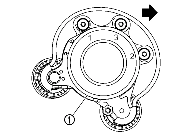
Exploded View
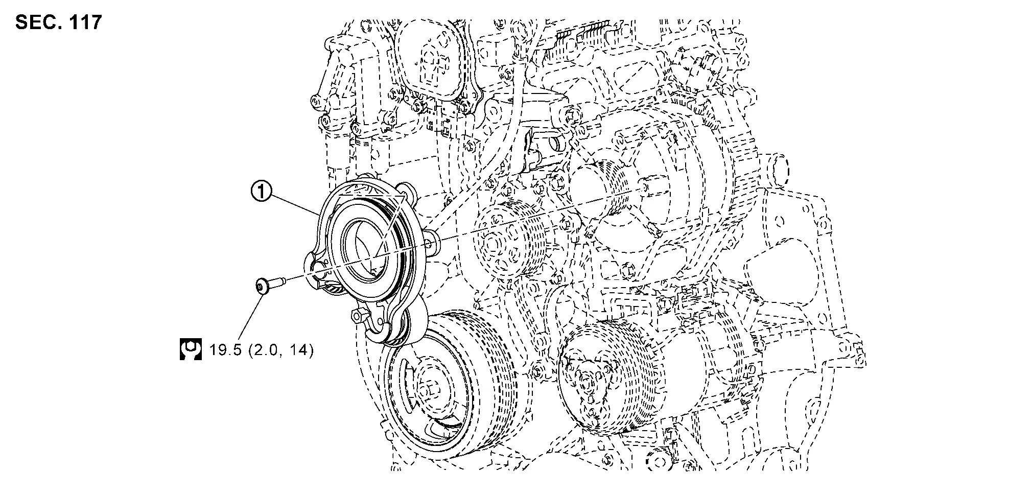
| 1. | Drive belt auto-tensioner | — | — | — | — |
Removal and Installation
REMOVAL
Remove the wheel and tire (front RH). Refer to Removal & Installation.
Remove the splash guard (front RH). Refer to Exploded View.
Remove the front spoiler. Refer to Removal and Installation.
Remove the fender protector (RH) front side clip and keep a service area. Refer to Removal and Installation.
Securely hold the hexagonal part (A) of the drive belt auto-tensioner
(1) with a suitable tool (C), and move it the direction of arrow ( ) (loosening direction of tensioner).
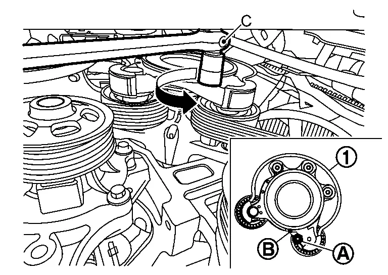
| B. | :Retaining hole |
Turn counterclockwise until the tensioner lock hole.
Insert a rod (C) approximately 4.0 mm (0.157 in.) in diameter through the rear of the drive belt auto-tensioner into retaining hole (B) to lock drive belt auto-tensioner pulley.
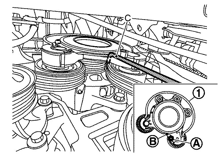
| 1. | :Drive belt auto-tensioner |
| A. | :Hexagonal part |
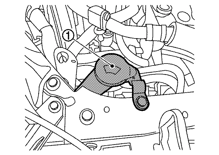
Remove the washer tank inlet (1).
Remove the drive belt auto-tensioner assembly bolts in the reverse sequence shown, and remove the drive belt auto-tensioner assembly (1).
Remove drive belt from drive belt auto-tensioner (if necessary).
-
Keep each drive belt auto-tensioner pulley arm locked after drive belts are removed.
INSTALLATION
If removed, install drive belt onto drive belt auto-tensioner pulley.
Install the drive belt auto-tensioner assembly (1) and tighten the bolts to the specified torque in the sequence shown.
 NOTE:
NOTE:
At this time, check that the drive belt is correctly set on the pulley of the drive belt auto-tensioner assembly.
| Drive belt auto-tensioner bolts | :19.5 Nm (2.0 kg-m,14 ft-lb) |
Install the drive belt onto all of the pulleys.
Release drive belt auto-tensioner assembly, and apply tension to drive belt.
Install the fender protector (RH). Refer to Removal and Installation.
Install the front spoiler. Refer to Removal and Installation.
Install the splash guard (front RH). Refer to Exploded View.
Install the wheel and tire (front RH). Refer to Removal & Installation.
Other materials:
Système d'essuie-glace automatique avec détecteur de pluie du Nissan Rogue
Le Nissan Rogue est doté d'une technologie de détection de précipitations intelligente. Ce système d'essuie-glace automatique, assisté par un capteur de pluie optique situé sur la partie supérieure du pare-brise (derrière le rétroviseur intérieur), est capable d'activer les balais sa ...
P026b Injection Timing
DTC Description
DTC DETECTION LOGIC DTC
CONSULT screen terms
(Trouble diagnosis content)
DTC detection condition
P026B
00
Injection timing
Diagnosis condition
—
Signal
—
Threshold
ECM does not control fuel injection timing properly when engine is running ...
Brake fluid
For more information on brake fluid type and capacity, refer to “Capacities and recommended fluids/lubricants”.
WARNING
Always use new brake fluid from a sealed container. Contaminated, old, or poor-quality fluid may damage the brake system and reduce stopping performance.
Clean the filler c ...