Nissan Rogue (T33) 2021-Present Service Manual: Diagnosis System (ecm)
Diagnosis Description
Driving Pattern
CAUTION:
Always drive at a safe speed.
DRIVING PATTERN A
Driving pattern A means a trip satisfying the following conditions.
-
Engine speed reaches 400 rpm or more.
-
Engine coolant temperature rises by 20ÂḞC (36ÂḞF) or more after starting the engine.
-
Engine coolant temperature reaches 70ÂḞC (158ÂḞF) or more.
-
The ignition switch is turned from ON to OFF.
 NOTE:
NOTE:
-
When the same malfunction is detected regardless of driving conditions, reset the counter of driving pattern A.
-
When the above conditions are satisfied without detecting the same malfunction, reset the counter of driving pattern A.
DRIVING PATTERN B
Driving pattern B means a trip satisfying the following conditions.
-
Engine speed reaches 400 rpm or more.
-
Engine coolant temperature reaches 70ÂḞC (158ÂḞF) or more.
-
Nissan Ariya Vehicle speed of 70 â 120 km/h (44 â 75 MPH) is maintained for 60 seconds or more under the control of closed loop.
-
Nissan Ariya Vehicle speed of 30 â 60 km/h (19 â 37 MPH) is maintained for 10 seconds or more under the control of closed loop.
-
Under the closed loop control condition, the following state reaches 12 seconds or more in total: Nissan Ariya Vehicle speed of 4 km/h (2 MPH) or less with idling condition.
-
The state of driving at 10 km/h (7 MPH) or more reaches 10 minutes or more in total.
-
A lapse of 22 minutes or more after engine start.
NOTE:
-
Drive the vehicle at a constant velocity.
-
When the same malfunction is detected regardless of driving conditions, reset the counter of driving pattern B.
-
When the above conditions are satisfied without detecting the same malfunction, reset the counter of driving pattern B.
DRIVING PATTERN C
Driving pattern C means operating vehicle as per the following:
The following conditions should be satisfied at the same time:
Engine speed: (Engine speed in the freeze frame data) Âḟ375 rpm
Calculated load value: (Calculated load value in the freeze frame data) x (1Âḟ0.1) [%]
Engine coolant temperature condition:
-
When the freeze frame data shows lower than 70ÂḞC (158ÂḞF), engine coolant temperature should be lower than 70ÂḞC (158ÂḞF).
-
When the freeze frame data shows higher than or equal to 70ÂḞC (158ÂḞF), engine coolant temperature should be higher than or equal to 70ÂḞC (158ÂḞF).
NOTE:
-
When the same malfunction is detected regardless of the above Nissan Ariya vehicle conditions, reset the counter of driving pattern C.
-
When the above conditions are satisfied without detecting the same malfunction, reset the counter of driving pattern C.
-
The 1st trip DTC will be cleared when C counter is counted once without the same malfunction after DTC is stored in ECM.
DRIVING PATTERN D
Driving pattern D means a trip satisfying the following conditions.
-
The state of driving at 40 km/h (25 MPH) reaches 300 seconds or more in total.
-
Idle speed lasts 30 seconds or more.
-
A lapse of 600 seconds or more after engine start.
NOTE:
-
When the same malfunction is detected regardless of driving conditions, reset the counter of driving pattern D.
-
When the above conditions are satisfied without detecting the same malfunction, reset the counter of driving pattern D.
CONSULT Function
FUNCTION
| Diagnostic test mode | Function |
|---|---|
| Self Diagnostic Result | Self-diagnostic results such as 1st trip DTC, DTCs and 1st trip freeze frame data or freeze frame data can be read and erased quickly.* Display non-network DTC which ECM memorizes. |
| Data Monitor | Input/Output data in the ECM can be read. |
| Work Support | This mode enables a technician to adjust some devices faster and more accurately by following the indications on the CONSULT unit. |
| Active Test | Diagnostic Test Mode in which CONSULT drives some actuators apart from the ECMs and also shifts some parameters in a specified range. |
| ECU Identification | ECM part number can be read. |
| Replace ECU | Function to READ/WRITE Nissan Ariya vehicle configuration. |
| DTC Work Support | SRT and operating condition to check DTC can be confirmed. |
*: The following emission-related diagnostic information is cleared when the ECM memory is erased.
-
DTC (Diagnostic trouble codes)
-
1st trip diagnostic trouble codes
-
Freeze frame data
-
1st trip freeze frame data
-
System readiness test (SRT) codes
-
Test values
SELF DIAGNOSTIC RESULT MODE
Self Diagnostic Item
Regarding items of DTC and 1st trip DTC, Refer to DTC Index.
How to Read DTC and 1st Trip DTC
DTCs and 1st trip DTCs related to the malfunction are displayed in âSelf-diag resultsâ mode with CONSULT. âTIMEâ indicates the number of driving the Nissan Ariya vehicle after the last detection of DTC.
-
When ECM has detected a current DTC, â0â is displayed for âTIMEâ.
-
When ECM memorizes a 1st trip DTC, â1tâ is displayed for âTIMEâ.
-
If âTIMEâ is neither â0â nor â1tâ, the DTC occurred in the past.
How to Erase DTC
NOTE:
If the ignition switch stays ON after repair work, be sure to turn ignition switch OFF once. Wait at least 10 seconds and then turn it ON (engine stopped) again.
Freeze Frame Data and 1st Trip Freeze Frame Data
| Freeze frame data item*1 | Description |
|---|---|
| Fuel system bank 1 |
|
| Fuel system bank 2 | |
| Calculated load value [%] | The calculated load value at the moment a malfunction is detected is displayed. |
| Coolant temperature [ÂḞC] | The engine coolant temperature at the moment a malfunction is detected is displayed. |
| L-Fuel Trim-bank1 [%] |
|
| L-Fuel Trim-bank2 [%] | |
| S-Fuel Trim-bank1 [%] |
|
| S-Fuel Trim-bank2 [%] | |
| Engine speed [rpm] | The engine speed at the moment a malfunction is detected is displayed. |
| Nissan Ariya Vehicle speed [km/h] or [mph] | The vehicle speed at the moment a malfunction is detected is displayed. |
| Intake manifold pressure [kPa] |
|
| ABSOL THÂṖP/S [%] | The throttle valve opening angle at the moment a malfunction is detected is displayed. |
| Base fuel schedule [msec] | The base fuel schedule at the moment a malfunction is detected is displayed |
| Intake air temperature [ÂḞC] or [ÂḞF] | The intake air temperature at the moment a malfunction is detected is displayed. |
| Combust condition |
|
| Fuel rail pressure [MPa] | The fuel rail pressure at the moment a malfunction is detected is displayed. |
| Target fuel rail pressure [MPa] | The target fuel rail pressure at the moment a malfunction is detected is displayed. |
| Battery voltage [V] | The battery voltage at the moment a malfunction is detected is displayed. |
| Fuel level [%] | The fuel level at the moment a malfunction is detected is displayed. |
*1: The items are the same as those of 1st trip freeze frame data.
DATA MONITOR MODE
NOTE:
-
The following table includes information (items) inapplicable to this Nissan Ariya vehicle. For information (items) applicable to this vehicle, refer to CONSULT display items.
-
For reference values of the following items, Refer to Physical Values.
Monitored Item
| Monitored item | Unit | Description | Remarks |
|---|---|---|---|
| Coolant temperature | ÂḞC | The engine coolant temperature (determined by the signal voltage of the engine outlet coolant temperature sensor) is displayed. | When the engine coolant temperature sensor is open or short-circuited, ECM enters fail-safe mode.The engine coolant temperature determined by the ECM is displayed. |
| Nissan Ariya Vehicle speed sensor | km/h or mph | The Nissan Ariya vehicle speed computed from the vehicle speed signal sent from combination meter is displayed. | |
| BATTERY VOLT | V | The power supply voltage of ECM is displayed. | |
| EGR TEMP SEN | V | The signal voltage of EGR temperature sensor is displayed. | |
| Intake air temperature | ÂḞC or ÂḞF | The intake air temperature (determined by the signal voltage of the intake air temperature sensor) is indicated. | |
| Ignition timing | BTDC | Indicates the ignition timing computed by ECM according to the input signals. | When the engine is stopped, a certain value is indicated. |
| ADM/V motor opening angle | deg | The opening becomes larger as the value increases. | |
| Barometric pressure sensor | V | The admission valve motor position signal voltage is displayed. | |
| Turbo boost presure sensor | V | The turbocharger boost sensor signal voltage is displayed. | |
| Purge control solenoid valve | % |
|
|
| Fuel tank temperature sensor | ÂḞC or ÂḞF | The fuel temperature (determined by the signal voltage of the fuel tank temperature sensor) is displayed. | |
| Speed limiter target Nissan Ariya vehicle speed | V | The signal voltage of the fuel level sensor is displayed. | |
| EVAP system pressure | V | The signal voltage of EVAP control system pressure sensor is displayed. | |
| Calculated load value | % | âCalculated load valueâ indicates the value of the current air flow divided by peak air flow. | |
| Heater oxygen sensor 2 (bank 1) | V | The signal voltage of the heated oxygen sensor 2 is displayed. | |
| Engine oil temperature | ÂḞCÂḞF | The engine oil temperature (determined by the signal voltage of the engine oil temperature sensor) is displayed. | |
| ATOM PRESS SEN | V | The atmospheric pressure sensor signal voltage is displayed. | |
| Manifold absolute pressure sensor | V | The atmospheric pressure sensor signal voltage is displayed, | |
| Air fuel ratio compensation (bank 1) | % | The mean value of the air-fuel ratio feedback correction factor per cycle is indicated. |
|
| A/F S1 HTR (B1) | % |
|
|
| EGR differential pressure | kPa | Displays ECM-calculated pressure difference between before and behind the EGR volume control valve. | |
| Exhaust VTC angle (bank 1) | ÂḞCA | Indicates [ÂḞCA] of exhaust camshaft advance angle. | |
| Wastegate valve closed position learning bank 2 | INCMP/ CMPLT |
Displays âfull close position learningâ experience of wastegate actuator.
|
|
| Wastegate valve closed position learning bank 1 | INCMP/CMPLT |
Displays âfull close position learningâ experience of wastegate actuator.
|
After replacing ECM, âINCMPâ is displayed. |
| EGR valve position | deg | ECM-calculated EGR valve position is displayed. | |
| Wastegate actuator position bank 1 | m | Indicates real stroke position of turbocharger wastegate actuator. The value is calculated by ECM based on the difference voltage between position sensor output and valve close position. | |
| Charge air cooler coolant temp | deg | The charge air cooler coolant temperature (determined by the signal voltage of the charge air cooler coolant temperature sensor) is displayed. | |
| Fan duty | % | Indicates a command value for cooling fan. The value is calculated by ECM based on input signals. | |
| Fuel pump duty | % | The control condition of the fuel pump control module (FPCM) (determined by ECM according to the input signals) is indicated. | |
| THRTL STK CNT B1 | â |
These items are displayed but are not applicable to this model. |
|
| A/GRLL SHTTR POSITION |
F/CLOSE MOVING F/OPEN UNIDTF |
Indicates the status of active grille shutter.
|
|
| ENG SPEED | rpm | Indicates the engine speed computed from the signal of the crankshaft position sensor and camshaft position sensor. | Accuracy becomes poor if engine speed drops below the idle rpm. |
| Travel after MIL ON | km or mile | Distance traveled while MIL is activated. | |
| Mass air flow sensor bank 1 | g/s | The signal flow rate of the mass air flow sensor is displayed. | |
| FUEL RAIL PRESSURE | ms | âBase fuel scheduleâindicates the fuel injection pulse width programmed into ECM, prior to any learned on board correction. |
Specification value is indicated on monitor screen under the following conditions.
|
| Mass air flow sensor | g/s | Indicates the mass air flow computed by ECM according to the mass air flow sensor signal. | |
| FUEL PRES SEN | MPa | Indicates the fuel rail pressure computed by ECM according to the input signals. | |
| Accelerate sensor 1 | V | The signal voltage of the accelerator pedal position sensor 1 is displayed. | |
| Accelerate sensor 2 | V | The converted value of the accelerator pedal position sensor signal voltage is displayed. | Accelerate sensor 2 signal is converted by ECM internally. Thus, they differs from ECM terminal voltage signal. |
| Throttle sensor 1 (bank 1) | V | The signal voltage of the throttle position sensor 1 B1 is displayed. | |
| Throttle sensor 2 (bank 1) | V | The value converted from the signal voltage of the throttle position sensor 2 B1 is displayed. | Throttle sensor 2 (bank 1) signal is converted by ECM internally. Thus, they differs from ECM terminal voltage signal. |
| Input pully speed | rpm | Indicates the engine speed computed from the input shaft revolution signal. | |
| Nissan Ariya Vehicle speed | km/h or mph | The Nissan Ariya vehicle speed computed from the vehicle speed signal sent from TCM is displayed. | |
| AC pressure sensor | V | The signal voltage from the refrigerant pressure sensor is displayed. | |
| Air/Fuel sensor1 (bank 1) | V | The A/F signal voltage computed from the input signal of the air fuel ratio (A/F) sensor 1 is displayed. | |
| Nissan Ariya Vehicle speed sensor | km/h or mph | The Nissan Ariya vehicle speed computed from the vehicle speed signal sent from combination meter is displayed. | |
| Exhaust VTC ïỳbank 1ïỳ | % |
|
|
| Air fuel ratio adjustment (bank 1) | â | Indicates the correction of a factor stored in ECM. The factor is calculated from the difference between the target air-fuel ratio stored in ECM and the air-fuel ratio calculated from A/F sensor 1 signal. | |
| Intake VTC angle (bank 1) | ÂḞCA | Indicates [ÂḞCA] of intake camshaft advance angle. | |
| High/Pressure fuel pump angle | deg | Displays ECM-calculated fuel discharge position of the high pressure fuel pump. | |
| Fuel pressure sensor voltage | mV | The signal voltage of FRP sensor is displayed. | |
| Engine oil pressure sensor | mV | The signal voltage of EOP sensor is displayed. | |
| EGR valve position sensor | V | ||
| Charge air cooler temperature sensor bank 1 | mV | The charge air cooler temperature (determined by the signal voltage of the charge air cooler temperature sensor) is displayed. | |
| Wastegate actuator position sensor bank 1 | V | Indicates position sensor output voltage of turbocharger wastegate actuator. | |
| Engine coolant bypass valve position | deg | The Multi-way Control Valve position detected by the position sensor is displayed. | |
| TOTAL DISTNC-OCS RST 1 | The Multi-way Control Valve position detected by the position sensor is displayed. | ||
| TOTAL DISTNC-OCS RST 2 | Total travel distance of odd meter when Oil Control System is reset. | ||
| TOTAL DISTNC-OCS RST 3 | Total travel distance of odd meter when Oil Control System is reset. (two times ago) | ||
| DETERIORTN VL-OCS RST 1 | Total travel distance of odd meter when Oil Control System is reset. (three times ago) | ||
| DETERIORTN VL-OCS RST 2 | Insicates deterioration condition of the engine oil when Oil Control System is reset. | ||
| DETERIORTN VL-OCS RST 3 | Insicates deterioration condition of the engine oil when Oil Control System is reset. (three times ago) | ||
| TOTAL DISTNC-OCS WRN 1 | Total travel distance of odd meter when Oil Control System remaining distance is zero. | ||
| TOTAL DISTNC-OCS WRN 2 | Total travel distance of odd meter when Oil Control System remaining distance is zero. (two times ago) | ||
| TOTAL DISTNC-OCS WRN 3 | Total travel distance of odd meter when Oil Control System remaining distance is zero. (two times ago) | ||
| DETERIORIN VL-OCS WRN 1 | Insicates deterioration condition of the engine oil when Oil Control System remaining distance is zero. | ||
| DETERIORIN VL-OCS WRN 2 | Insicates deterioration condition of the engine oil when Oil Control System remaining distance is zero. (two times ago) | ||
| DETERIORIN VL-OCS WRN 3 | Insicates deterioration condition of the engine oil when Oil Control System remaining distance is zero. (three times ago) | ||
| CURRENT DETERIORANT VAL | Insicates deterioration condition of the engine oil. | ||
| Engine basis parts value 1 | These items are displayed but not used. | ||
| Engine basis parts value 2 | These items are displayed but not used. | ||
| Electric water pump 1 duty | % | The control condition of the charge air cooler cooling electric water pump (determined by ECM according to the input signals) is indicated. | |
| Injection total fuel mass (B1) | mg/cycle | Indicates the total fuel injection volume computed by ECM according to the input signals. | |
| Cylinder intake air mass | mg/cycle | Indicates the intake air volume computed by ECM according to the input signals. | |
| Lower limit int air mass (IDLE) | mg/cycle | Indicates the lower limit of intake air volume computed by ECM according to the input signals. | |
| Upper limit int air mass (IDLE) | mg/cycle | Indicates the upper limit of intake air volume computed by ECM according to the input signals. | |
| LOAD SIGNAL | On/Off |
Indicates [On/Off] condition of the electrical load signal.
|
|
| AIR COND SIG | On/Off | Indicates [On/Off] condition of the air conditioner switch as determined by the air conditioner signal. | |
| PW/ST SIGNAL | On/Off | Indicates [On/Off] condition of the power steering system (determined by the signal voltage of the power steering pressure sensor signal). | |
| P/N POSI SW | On/Off | Indicates [On/Off] condition from the reverse/neutral position signal. | |
| START SIGNAL | On/Off | Indicates start signal status [On/Off] computed by the ECM according to the signals of engine speed and battery voltage. | After starting the engine, [Off] is displayed regardless of the starter signal. |
| CLSD THL POS | On/Off | Indicates idle position [On/Off] computed by ECM according to the accelerator pedal position sensor signal. | |
| HO2S2 MNTR(B1) | RICH/LEAN |
Display of heated oxygen sensor 2 signal: RICH: means the amount of oxygen after three way catalyst is relatively small. LEAN: means the amount of oxygen after three way catalyst is relatively large. |
When the engine is stopped, a certain value is indicated. |
| IGNITION SW | On/Off | Indicates [On/Off] condition from ignition switch signal. | |
| HEATER FAN SW | On/Off | Indicates [On/Off] condition from the heater blower ON signal. | |
| IDL A/V LEARN | YET/CMPLT |
Displays the condition of Idle Air Volume Learning.
|
|
| Brake switch | On/Off | Indicates [On/Off] condition from the stop lamp switch signal. | |
| COMBUSTION | These items are displayed but not used. | ||
| AIR COND RLY | On/Off | The air conditioner relay control condition (determined by ECM according to the input signals) is indicated. | |
| Fuel pump relay | On/Off | Indicates the fuel pump relay control condition determined by ECM according to the input signals. | |
| FPCM | Hi/Mid/ Low/Off | The control condition of the fuel pump control module (FPCM) (determined by ECM according to the input signals) is indicated. | |
| VENT CONT/V | On/Off |
The control condition of the EVAP canister vent control valve (determined by ECM according to the input signals) is indicated.
|
|
| Heated oxygen sensor heater 2 bank 1 | On/Off | Indicates [On/Off] condition of heated oxygen sensor 2 heater determined by ECM according to the input signals. | |
| Brake operation judgment | On/Off | Indicates [On/Off] condition of Brake operation judgment. | |
| DIST SW | On/Off | Indicates [On/Off] condition from DISTANCE switch signal. | |
| Brake switch2 | On/Off | Indicates [On/Off] condition of stop lamp switch signal. | |
| Brake switch1 | On/Off | Indicates [On/Off] condition from stop lamp switch signal. | |
| SET SW | On/Off | Indicates [On/Off] condition from SETâ switch signal. | |
| RESUME/ACC SW | On/Off | Indicates [On/Off] condition from RES+ switch signal. | |
| CANCEL SW | On/Off | Indicates [On/Off] condition from CANCEL switch signal. | |
| MAIN SW | On/Off | Indicates [On/Off] condition from MAIN switch signal. | |
| CRUISE LAMP | On/Off | Indicates [On/Off] condition of CRUISE indicator determined by the ECM according to the input signals. | |
| A/GRLL SHTTR CALIBRATION | INCMP/ CMPLT |
Indicates initial position learning status of active grille shutter.
|
|
| A/GRLL SHTTR CIRCUIT DIAG | OK/NG |
Indicates the diagnosis result of active grille shutter circuit.
|
|
| A/GRLL SHTTR TEMP DIAG | OK/NG |
Indicates the diagnosis result of active grille shutter actuator temperature status.
|
|
| A/GRLL SHTTR OVER RUN | OK/NG |
Indicates active grille shutter moves beyond normal moving limit.
|
|
| A/GRLL SHTTR STUCK | OK/NG |
Indicates the diagnosis result of active grille shutter stuck or the operation range less than normal.
|
|
| A/GRLL SHTTR CALIB DIAG | OK/NG |
Indicates the diagnosis result of initial position learning of active grille shutter.
|
|
| HO2 S2 DIAG1 (B1) | INCMP/CMPLT |
Indicates DTC P0139 self-diagnosis (delayed response) condition.
|
|
| HO2 S2 DIAG2 (B1) | INCMP/CMPLT |
Indicates DTC P0139 self-diagnosis (slow response) condition.
|
|
| EVAP LEAK DIAG | YET/CMPLT |
Indicates the condition of EVAP leak diagnosis.
|
|
| EVAP DIAG READY | On/Off |
Indicates the ready condition of EVAP leak diagnosis.
|
|
| SYSTEM 1 DIAGNOSIS A B1 | INCMP/CMPLT |
Indicates DTC P219A self-diagnosis condition.
|
|
| A/F SEN1 DIAG1 (B1) | INCMP/CMPLT |
|
|
| A/F SEN1 DIAG2(B1) | INCMP/CMPLT |
Indicates DTC P014C or P014D self-diagnosis condition.
|
|
| SYSTEM 1 DIAGNOSIS B B1 | ABSNT/PRSNT |
|
|
| A/F IMBALNC DIAG-CPS STAT | ABSNT/PRSNT |
Indicates DTC P219C - P219F self diagnosis condition.
|
|
| A/F SEN1 DIAG3(B1) | ABSNT/PRSNT |
Indicates DTC P014C, P014D, P015A or P015B self-diagnosis condition.
|
|
| A/F IMBLNC DIAG-CPS CMPLT | INCMP/CMPLT |
Indicates DTC P219C - P219F self diagnosis condition.
|
|
| VCR actual shaft 2 angle | Indicates VCR control shaft 2 angle. | ||
| Cooling fan | These items are displayed but not used. | ||
| Injector offset learning status | â | Indicates condition of Injector Offset learning status. | |
| Di inj pulse B1 | msec | ECM-calculated injection pulse width of the direct fuel injector on the bank 1 side. | |
| Starter motor (Counter) | OK/NG | When the starter motor exceeds the specified No. of starting operation, NG is displayed. | |
| Driver's seat belt switch | OK/NG | When the malfunction of the Driver's seat belt switch is judged, OK or NG is displayed. | |
| Engine parts | OK/NG | When the malfunction of the Driver's seat belt switch is judged, OK or NG is displayed. | |
| ABS error | OK/NG | When an ABS abnormality is received from the ABS actuator and electric unit, NG is displayed. | |
| TCM error | OK/NG | When an CVT abnormality is received from the TCM, NG is displayed. | |
| TCM error B | OK/NG | When an DTC abnormality is received from the TCM, NG is displayed. | |
| VDC error | OK/NG | When an VDC abnormality is received from the ABS actuator and electric unit, NG is displayed. | |
| IPDM error | OK/NG | When an abnormal voltage status is received from the IPDM E/R, NG is displayed. | |
| CAN comm (VDC) A | OK/NG | When the communication status with the ABS actuator and electric unit is judged, OK or NG is displayed. | |
| CAN comm (VDC) B | OK/NG | When the communication status with the ABS actuator and electric unit is judged, OK or NG is displayed. | |
| CAN comm (VDC) C | OK/NG | When VDC is judged based on the communication status with the ABS actuator and electric unit, OK or NG is displayed. | |
| CAN comm (VDC) D | OK/NG | When VDC is judged based on the communication status with the ABS actuator and electric unit, OK or NG is displayed. | |
| CAN comm (VDC) E | OK/NG | When VDC is judged based on the communication status with the ABS actuator and electric unit, OK or NG is displayed. | |
| CAN comm (VDC) F | OK/NG | When VDC is judged based on the communication status with the ABS actuator and electric unit, OK or NG is displayed. | |
| CAN comm (VDC) G | OK/NG | When VDC is judged based on the communication status with the ABS actuator and electric unit, OK or NG is displayed. | |
| CAN comm (VDC) H | OK/NG | When VDC is judged based on the communication status with the ABS actuator and electric unit, OK or NG is displayed. | |
| CAN comm (TCM) A | OK/NG | When A/T is judged based on the communication status with the TCM, OK or NG is displayed. | |
| CAN comm (TCM) B | OK/NG | When CVT is judged based on the communication status with the TCM, OK or NG is displayed. | |
| CAN comm (TCM) C | OK/NG | When A/T is judged based on the communication status with the TCM, OK or NG is displayed. | |
| CAN comm (TCM) D | OK/NG | When CVT is judged based on the communication status with the TCM, OK or NG is displayed. | |
| CAN comm (TCM) E | OK/NG | When A/T is judged based on the communication status with the TCM, OK or NG is displayed. | |
| CAN comm (BCM) A | OK/NG | When the communication status with the BCM is judged, OK or NG is displayed. | |
| CAN comm (BCM) B | OK/NG | When the communication status with the BCM is judged, OK or NG is displayed. | |
| CAN comm (BCM) C | OK/NG | When the communication status with the BCM is judged, OK or NG is displayed. | |
| CAN comm (BCM) D | OK/NG | When the communication status with the BCM is judged, OK or NG is displayed. | |
| CAN comm (BCM) E | OK/NG | When the communication status with the BCM is judged, OK or NG is displayed. | |
| CAN comm (IPDM) A | OK/NG | When the communication status with the IPDM E/R is judged, OK or NG is displayed. | |
| CAN comm (IPDM) B | OK/NG | When the communication status with the IPDM E/R is judged, OK or NG is displayed. | |
| CAN comm (IPDM) C | OK/NG | When the communication status with the IPDM E/R is judged, OK or NG is displayed. | |
| CAN comm (IPDM) D | OK/NG | When the communication status with the IPDM E/R is judged, OK or NG is displayed. | |
| CAN comm (IPDM) E | OK/NG | When the communication status with the IPDM E/R is judged, OK or NG is displayed. | |
| Starter motor relay | OK/NG | When the malfunction of the ST/IS relay is judged, OK or NG is displayed. | |
| Neutral switch | OK/NG | When the malfunction of the neutral switch is judged, OK or NG is displayed. | |
| Clutch switch (Lower) | OK/NG | When the malfunction of the Clutch switch (Lower) is judged, OK or NG is displayed. | |
| Clutch switch (Upper) | OK/NG | When the malfunction of the Clutch switch (Upper) is judged, OK or NG is displayed. | |
| CAN comm (EPS) | OK/NG | When the communication status with the steering control module is judged, OK or NG is displayed. | |
| LIN comm (DC/DC) | OK/NG | When the malfunction of DC/DC converter is received from LIN communication status, OK or NG is displayed. | |
| Negative pressure | OK/NG | When the brake booster pressure sensor status is judged, OK or NG is displayed. | |
| Air fuel ration learning counter (bank 1) | â |
This item is displayed but are not applicable to this model. |
|
| TRGT ALT VLTG | V | Indicates a command value for sub starter & generator. The value is calculated by ECM based on input signals. |
WORK SUPPORT MODE
Work Item
| Work item | Condition | Usage |
|---|---|---|
| EVAP SYSTEM CLOSE |
Close the EVAP canister vent control valve in order to make EVAP system close under the following conditions.
|
When detecting EVAP vapor leak in the EVAP system |
| MAC KEY writing | Ignition switch: ON | Write MAC key to ECM. |
| WASTEGATE ACTUATOR POSI LEARN VALUE CLEAR | Ignition switch is ON and Engine running | When learning full close position of wastegate actuator after ECM or turbocharger assembly is replaced. |
| Misfire count (past) | These items are displayed but not used. | |
| Engine basis parts value 1 and 2 clear | This item is displayed but not used. | |
| VCR base position learning | In this mode, learning of VCR base position. | When VCR control module or VCR actuator are replaced. |
| Close throttle position learning | Ignition switch ON and engine stopped. | When learning the throttle valve closed position |
| Air fuel ratio learning value clear | The coefficient of self-learning control mixture ratio returns to the original coefficient. | When clearing mixture ratio selflearning value |
| Air fuel ratio initial learning | Air fuel ratio learning frequency is low while idling, learning the air fuel ratio of the idling domain in ECM. | When learning the air fuel ratio. |
| VALVE TIMING ADJUSTMENT | These items are displayed but not used. | |
| VIN REGISTRATION | In this mode, VIN is registered in ECM. | When registering VIN in ECM |
| Electric intake valve timing control learning | Ignition switch ON and engine stopped. |
After the following parts are replaced.
|
| Misfire count (real-time) | These items are displayed but not used. | |
| EGR control valve closed position learning | Ignition switch: ON | When learning closed position of the EGR volume control valve. |
| Idle air volume learning | The idle air volume that keeps the engine speed within the specified range is memorized in ECM. | When learning the idle air volume |
| Target ignition timing adjustment* | Idle condition | When adjusting target ignition timing |
| Target idle RPM adjustment* | Idle condition | When setting target idle speed |
| Engine coolant bypass valve A | Condition: The valve is in the full opening position | When filing with coolant. |
| SAVING DATA FOR REPLC CPU | In this mode, save data that is in ECM. | When ECM is replaced. |
| WRITING DATA FOR REPLC CPU | In this mode, write data stored by âSAVE DATA FOR CPU REPLCâ in work support mode to ECM. | When ECM is replaced. |
| Fuel injector offset learning | Idle condition | When ECM or injector are replaced. |
| Stop/Start prohibit cause data recorder | Ignition switch: ON (Engine stopped) | Indicates the reason that stop/start system does not operate when Nissan Ariya vehicle is stopped on CONSULT. |
| Stop/Start engine stall cause data recorder | Ignition switch: ON (Engine stopped) | Indicates the reason that engine is stalled on CONSULT. |
| Stop/Start engine restart cause data recorder | Ignition switch: ON (Engine stopped) | Indicates the reason that engine is restarted when stop/start system operates on CONSULT. |
| DTC history | Ignition switch: ON | When the symptom described by the customer but there is no DTC on âAll DTCâ of CONSULT. |
ACTIVE TEST MODE
Test Item
| TEST ITEM | CONDITION | JUDGMENT | CHECK ITEM (REMEDY) |
|---|---|---|---|
| Engine Coolant temperature | Change the engine coolant temperature using CONSULT. | If malfunctioning symptom disappears, see CHECK ITEM. |
|
| FUEL INJECTION | Change the amount of fuel injection using CONSULT. | If malfunctioning symptom disappears, see CHECK ITEM. |
|
| IGNITION TIMING |
|
If malfunctioning symptom disappears, see CHECK ITEM. | Perform Idle Air Volume Learning. |
| PURG VOL CONT/V |
|
Engine speed changes according to the opening percent. |
|
| FUEL/T TEMP SEN | Change the fuel tank temperature using CONSULT. | ||
| POWER BALANCE |
|
Engine runs rough or stops. (Works for accidental fire.) |
|
| Intake valve timing angle | Changes intake valve timing using CONSULT. | If malfunctioning symptom disappears, see CHECK ITEM. |
|
| EXT V/T ASSIGN ANGLE | Changes exhaust valve timing using CONSULT. | If malfunctioning symptom disappears, see CHECK ITEM. |
|
| FPCM |
|
Fuel pump speed changes or stops. |
|
| EVAP canister vent control valve |
|
EVAP canister vent control valve makes an operating sound. |
|
| EGR CONTROL VALVE |
|
Valve opening angle changes according to target angle (from 0deg to 70deg) |
|
| WASTEGATE ACTUATOR |
|
Wastegate valve position sensor voltage changes according to valve target angle |
|
| Turbocharger bypass valve |
|
Bypass valve makes the operating sound. |
|
| Fan duty control* |
|
Cooling fan speed changes. |
|
| ACTIVE GRILLE SHUTTER |
To check the operation of the active grille shutter, follow the steps below:
|
Active grille shutter fully opens or fully closes. |
|
| VCR system |
|
VCR control shaft 2 actual angle changes according to target angle |
|
| ADM/V motor target angle | Ignition switch: ON (Engine stopped) | Valve opening angle changes according to target angle. |
|
| Charge air cooler cooling electric water pump | Engine: Idle | Change the driving mode of charge air cooler electric water pump. |
|
| AUTO STOP START |
Engine: After warming up, run engine at idle
|
Check the stop/start system operate and restart. |
|
|
CAUTION:
|
|||
| ALTERNATOR VOLTAGE |
|
Battery voltage changes. |
|
*: Leaving cooling fan OFF with CONSULT while engine is running may cause the engine to overheat.
DTC WORK SUPPORT MODE
Test Item
| Test mode | Test item | Corresponding DTC No. | Reference page |
|---|---|---|---|
| HO2S2 | Heater oxygen sensor 2 (bank 1) P1146 | P0138 | DTC Description. |
| Heater oxygen sensor 2 (bank 1) P1147 | P0137 | DTC Description. | |
| Heater oxygen sensor 2 (bank 1) P0139 | P0139 | DTC Description. | |
| A/F SEN1 | Air/Fuel sensor1 (bank 1) P1276 | P0130 | DTC Description. |
| A/F SENSOR(B1) P014C/P014D | â | â | |
| EVAPORATIVE SYSTEM | PURG FLOW P0441 | P0441 | DTC Description. |
SRT STATUS Mode
-
For items whose SRT codes are set, âCMPLTâ is displayed on the CONSULT screen; for items whose SRT codes are not set, âINCMPâ is displayed.
-
âSRT STATUSâ provides the presence or absence of permanent DTCs stored in control module memory.
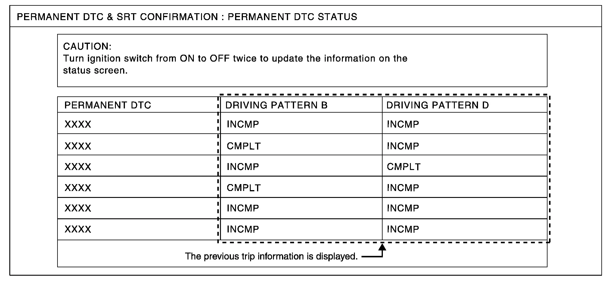
PERMANENT DTC STATUS Mode
How to Display Permanent DTC Status
-
Turn ignition switch OFF and wait at 10 seconds.
-
Turn ignition switch ON.
-
Turn ignition switch OFF and wait at 10 seconds.
-
Turn ignition switch ON.
-
Select âPERMANENT DTC STATUSâ in âDTC & SRT CONFIRMATIONâ mode with CONSULT.
NOTE:
Permanent DTCs stored in control module memory are displayed on the CONSULT screen to show if a driving pattern required for erasing permanent DTCs is complete (CMPLT) or incomplete (INCMP).
CAUTION:
Since the âPERMANENT DTC STATUSâ screen displays the previous trip information, repeat the following twice to update the information: âIgnition switch OFFâ, âWait for more than 10 secondsâ and âIgnition switch ONâ.
NOTE:
This mode is not used in regions that permanent DTCs are not regulated by law.
SRT WORK SUPPORT Mode
This mode enables a technician to drive a vehicle to set the SRT while monitoring the SRT status.
PERMANENT DTC WORK SUPPORT Mode
This mode enables a technician to drive a vehicle to complete the driving pattern that is required for erasing permanent DTC.
NOTE:
This mode is not used in regions that permanent DTCs are not regulated by law.
SRT STATUS Mode
For items whose SRT codes are set, âCMPLTâ is displayed on the CONSULT screen; for items whose SRTcodes are not set, âINCMPâ is displayed.
SRT WORK SUPPORT Mode
This mode enables a technician to drive a vehicle to set the SRT while monitoring the SRT status.
Other materials:
Three Way Catalyst
Exploded View
Air fuel ratio (A/F) sensor 1
Manifold washer
Stud bolt
Catalyst support bracket
Three way catalyst
Heated oxygen sensor 2
Turbo gasket (OUT)
V-band clamp
Comply with the assembly procedure when tightening. Refer to Remo ...
Removal and Installation. Battery Terminal with Fusible Link
Exploded View
Battery terminal with fusible link
: NÂṖm (kg-m, in-lb)
: NÂṖm (kg-m, ft-lb)
Removal and Installation
REMOVALDisconnect the battery cable from the negative terminal. Refer to Exploded View.
CAUTION:
To prevent damage to the parts, disc ...
Transaxle Assembly
Exploded View
O-ring
Tube A
Control valve
O-ring
Oil strainer
Oil pan gasket
Oil pan
Drain plug gasket
Drain plug
Magnet
O-ring
O-ring
Tube B
Lip seal
Transaxle assembly
: Always replace after every disassembly ...