Nissan Rogue (T33) 2021-Present Service Manual: Diagnosis and Repair Work Flow
Work Flow
Without ProPILOT Assist 2.1
OVERALL SEQUENCE
DETAILED FLOW
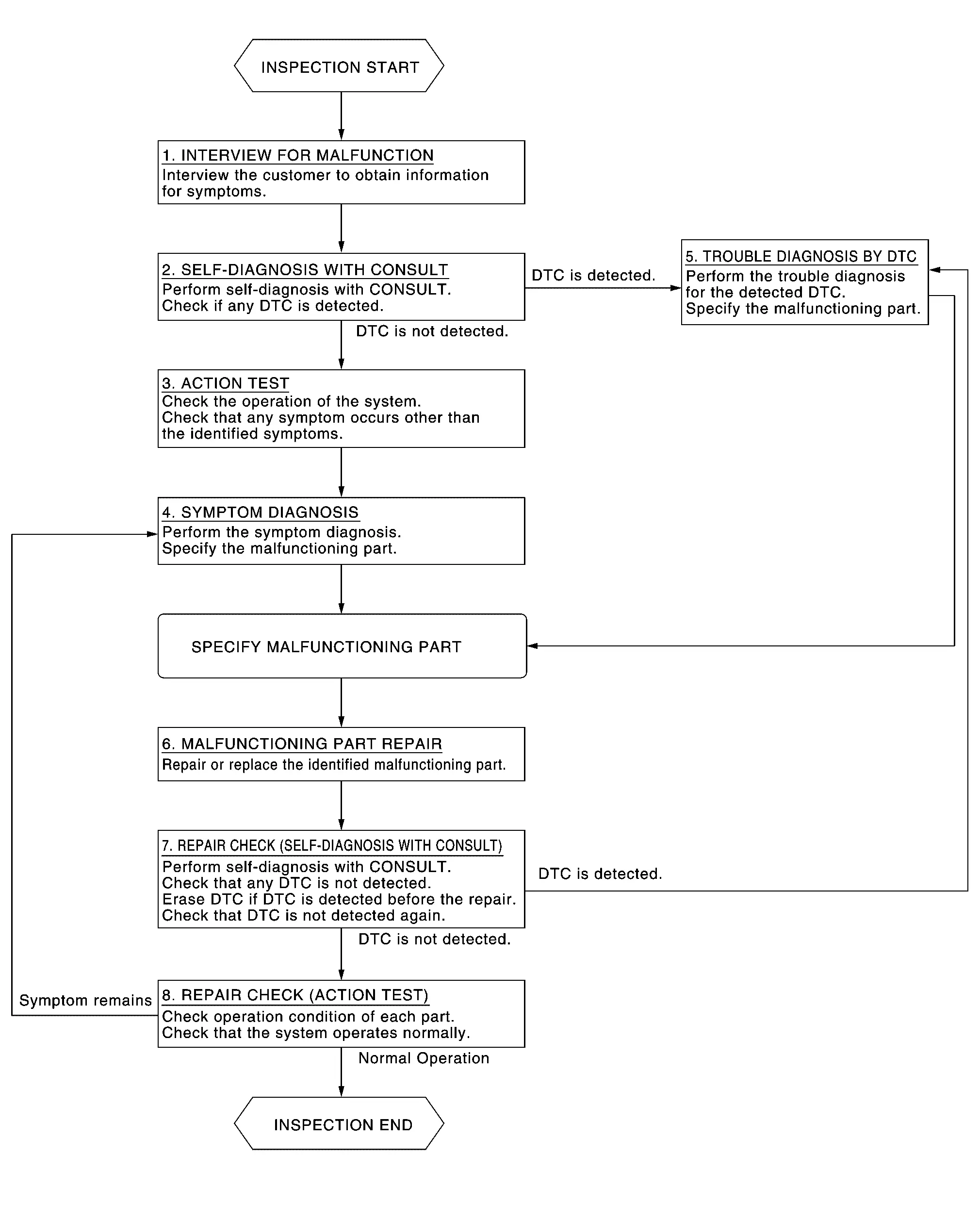
INTERVIEW FOR MALFUNCTION
It is important to clarify the customer’s concerns before starting the inspection. Interview the customer about the concerns carefully and understand the symptoms fully.
 NOTE:
NOTE:
The customers are not professionals. Never assume that “maybe the customer means...” or “maybe the customer mentioned this symptom”.
>>
GO TO 2.
SELF-DIAGNOSIS WITH CONSULT
 CONSULT
-
Perform “All DTC Reading” mode.
-
Check if the DTC is detected in the “Self Diagnostic Result” of the following:
-
“ICC/ADAS 2”
-
“LASER/RADAR”
-
“LANE CAMERA”
-
“Side radar (Rear left)”
-
“Side radar (Rear right)”
-
Is any DTC detected?
YES>>Record or print self-diagnosis results and freeze frame data (FFD).GO TO 5.
NO>>GO TO 3.
ACTION TEST
-
Perform the system action test to check the operation status of the following:
-
LDW: Refer to Work Procedure.
-
I-LI: Refer to Work Procedure.
-
BSW: Refer to Work Procedure.
-
I-BSI: Refer to Work Procedure.
-
TSR: Refer to Work Procedure.
-
RCTA: Refer to Work Procedure.
-
I-DA: Refer to Work Procedure.
-
-
Check if any other malfunctions occur.
>>
GO TO 4.
SYMPTOM DIAGNOSIS
Perform the applicable diagnosis according to the diagnosis chart by symptom. Refer to Symptom Table.
>>
GO TO 6.
TROUBLE DIAGNOSIS BY DTC
CONSULT
-
Erase self-diagnostic results.
-
Ignition switch OFF ‚Üí ON.
CAUTION:
Be sure to wait of 10 seconds after turning ignition switch OFF or ON.
-
Check the DTC in the “Self Diagnostic Result”.
-
Perform trouble diagnosis for the following detected DTC:
-
“ICC/ADAS 2”: Refer to DTC Index.
-
“LASER/RADAR”: Refer to DTC Index.
-
“LANE CAMERA”: Refer to DTC Index.
-
“Side radar (Rear left)”: Refer to DTC Index.
-
“Side radar (Rear right)”: Refer to DTC Index.
-
NOTE:
If Network-DTC is detected, first diagnose the CAN communication system.
>>
GO TO 6.
MALFUNCTIONING PART REPAIR
Repair or replace the identified malfunctioning parts.
>>
GO TO 7.
REPAIR CHECK (SELF-DIAGNOSIS WITH CONSULT)
-
Erase “Self Diagnostic Result”.
-
Perform “All DTC Reading” mode after repairing or replacing the specific items.
-
Check if any DTC is detected in self-diagnosis results of the following:
-
“ICC/ADAS 2”
-
“LASER/RADAR”
-
“LANE CAMERA”
-
“Side radar (Rear left)”
-
“Side radar (Rear right)”
-
Is any DTC detected?
YES>>GO TO 5.
NO>>GO TO 8.
REPAIR CHECK (ACTION TEST)
Perform the following system action test. Check that the malfunction symptom is solved or no other symptoms occur.
-
LDW: Refer to Work Procedure.
-
I-LI: Refer to Work Procedure.
-
BSW: Refer to Work Procedure.
-
I-BSI: Refer to Work Procedure.
-
TSR: Refer to Work Procedure.
-
RCTA: Refer to Work Procedure.
-
I-DA: Refer to Work Procedure.
Is there a malfunction symptom?
YES>>GO TO 4.
NO>>Inspection End.
With ProPILOT Assist 2.1
OVERALL SEQUENCE
DETAILED FLOW
INTERVIEW FOR MALFUNCTION
It is important to clarify the customer’s concerns before starting the inspection. Interview the customer about the concerns carefully and understand the symptoms fully.
NOTE:
The customers are not professionals. Never assume that “maybe the customer means...” or “maybe the customer mentioned this symptom”.
>>
GO TO 2.
SELF-DIAGNOSIS WITH CONSULT
CONSULT
-
Perform “All DTC Reading” mode.
-
Check if the DTC is detected in the “Self Diagnostic Result” of the following:
-
“ICC/ADAS 2”
-
“LASER/RADAR”
-
“LANE CAMERA”
-
“Side radar (Rear left)”
-
“Side radar (Rear right)”
-
“Side radar (Front left)”
-
“Side radar (Front right)”
-
"HD MAP"
-
"Driver Monitor Camera"
-
Is any DTC detected?
YES>>Record or print self-diagnosis results and freeze frame data (FFD).GO TO 5.
NO>>GO TO 3.
ACTION TEST
-
Perform the system action test to check the operation status of the following:
-
LDW: Refer to Work Procedure.
-
I-LI: Refer to Work Procedure.
-
BSW: Refer to Work Procedure.
-
I-BSI: Refer to Work Procedure.
-
TSR: Refer to Work Procedure.
-
RCTA: Refer to Work Procedure.
-
I-DA: Refer to Work Procedure.
-
“Side radar (Front left)”: Refer to System Description.
-
“Side radar (Front right)”: Refer to System Description.
-
"HD MAP": Refer to System Description.
-
"Driver Monitor Camera": Refer to System Description.
-
-
Check if any other malfunctions occur.
>>
GO TO 4.
SYMPTOM DIAGNOSIS
Perform the applicable diagnosis according to the diagnosis chart by symptom. Refer to Symptom Table.
>>
GO TO 6.
TROUBLE DIAGNOSIS BY DTC
CONSULT
-
Erase self-diagnostic results.
-
Ignition switch OFF ‚Üí ON.
CAUTION:
Be sure to wait of 10 seconds after turning ignition switch OFF or ON.
-
Check the DTC in the “Self Diagnostic Result”.
-
Perform trouble diagnosis for the following detected DTC:
-
“ICC/ADAS 2”: Refer to DTC Index.
-
“LASER/RADAR”: Refer to DTC Index.
-
“LANE CAMERA”: Refer to DTC Index.
-
“Side radar (Rear left)”: Refer to DTC Index.
-
“Side radar (Rear right)”: Refer to DTC Index.
-
NOTE:
If Network-DTC is detected, first diagnose the CAN communication system.
>>
GO TO 6.
MALFUNCTIONING PART REPAIR
Repair or replace the identified malfunctioning parts.
>>
GO TO 7.
REPAIR CHECK (SELF-DIAGNOSIS WITH CONSULT)
-
Erase “Self Diagnostic Result”.
-
Perform “All DTC Reading” mode after repairing or replacing the specific items.
-
Check if any DTC is detected in self-diagnosis results of the following:
-
“ICC/ADAS 2”
-
“LASER/RADAR”
-
“LANE CAMERA”
-
“Side radar (Rear left)”
-
“Side radar (Rear right)”
-
“Side radar (Front left)”
-
“Side radar (Front right)”
-
"HD MAP"
-
"Driver Monitor Camera"
-
Is any DTC detected?
YES>>GO TO 5.
NO>>GO TO 8.
REPAIR CHECK (ACTION TEST)
Perform the following system action test. Check that the malfunction symptom is solved or no other symptoms occur.
-
LDW: Refer to Work Procedure.
-
I-LI: Refer to Work Procedure.
-
BSW: Refer to Work Procedure.
-
I-BSI: Refer to Work Procedure.
-
TSR: Refer to Work Procedure.
-
RCTA: Refer to Work Procedure.
-
I-DA: Refer to Work Procedure.
Is there a malfunction symptom?
YES>>GO TO 4.
NO>>Inspection End.
Other materials:
Sièges, ceintures de sécurité et systèmes de retenue supplémentaires (SRS)
Dans le Nissan Rogue, la sécurité des occupants repose sur l’association des ceintures, des appuie-tête et des dispositifs SRS (airbags et capteurs). Reportez-vous toujours aux avertissements du manuel avant toute intervention sur un composant SRS.
Airbags avant : protection frontale du ...
Dtc/circuit Diagnosis. Power Supply and Ground Circuit
Moonroof Motor Assembly
Diagnosis Procedure
CHECK FUSE
Ignition switch OFF.
Check that the following fuse is not blown (open):
Fuse No. Capacity
31
15 A
Is the fuse blown (open)?
YES>>
Repair the blown (open) fuse after repairing the affected circuit if a fuse ...
C10b0-09 Parking Brake Actuator (rh)
DTC Description
DTC DETECTION LOGIC DTC No.
CONSULT screen terms
(Trouble diagnosis content) DTC detection condition
C10B0
09
Parking brake actuator (RH)
[Parking brake actuator (right)]
Diagnosis condition
When parking brake is apply
Signal (terminal)
—
Threshol ...