Nissan Rogue (T33) 2021-Present Service Manual: Removal and Installation :: Hood
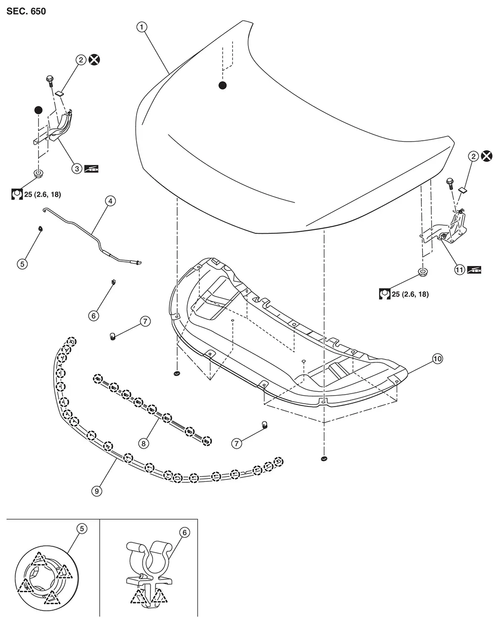
Exploded View
 |
Hood assembly |  |
Hood hinge seal |  |
Hood hinge RH |
 |
Hood support rod |  |
Hood support rod grommet |  |
Hood support rod clamp |
 |
Hood bumper rubber |  |
Radiator core seal |  |
Hood seal |
 |
Hood insulator |  |
Hood hinge LH | ||
 |
: Clip | ||||
 |
: Pawl | ||||
 |
: Always replace after every disassembly. | ||||
 |
: Body grease | ||||
 : Indicates that the part is connected at points with same symbol in actual Nissan Ariya vehicle. : Indicates that the part is connected at points with same symbol in actual Nissan Ariya vehicle. |
|||||
Hood Assembly
Removal and Installation
CAUTION:
-
Perform work with 2 workers, because it is heavy weight.
-
Support hood with a proper material and use protective tape or shop cloth to protect hood and body from falling and damage when removing and installing hood assembly.
REMOVAL
Support hood assembly with a proper material to prevent it from falling.
WARNING:
Injury may occur if hood assembly is not supported with a proper material when removing hood assembly.
Remove hood assembly mounting nuts, and then remove hood assembly.
INSTALLATION
Note the following items, and then install in the reverse order of removal.
CAUTION:
-
Before installation, apply anticorrosive agent onto mounting surface.
-
After installation, perform the fitting adjustment. Refer to Adjustment.
-
After installation, apply touch-up paint (the body color) if the paint around hinge is peeled off during removal.
-
After installation, check the open/close operation. Refer to Inspection.
Inspection
Open and close hood. Check that hood hinge rotation portion moves smoothly.
Check hood hinge rotating part for poor lubrication. If necessary, apply grease.
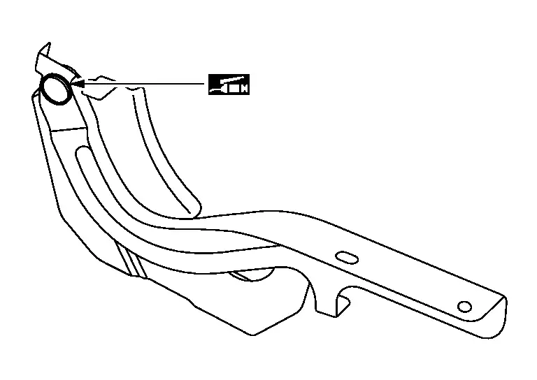
|
: Body grease |
Adjustment
FITTING ADJUSTMENT
Fitting Adjustment Standard Dimension
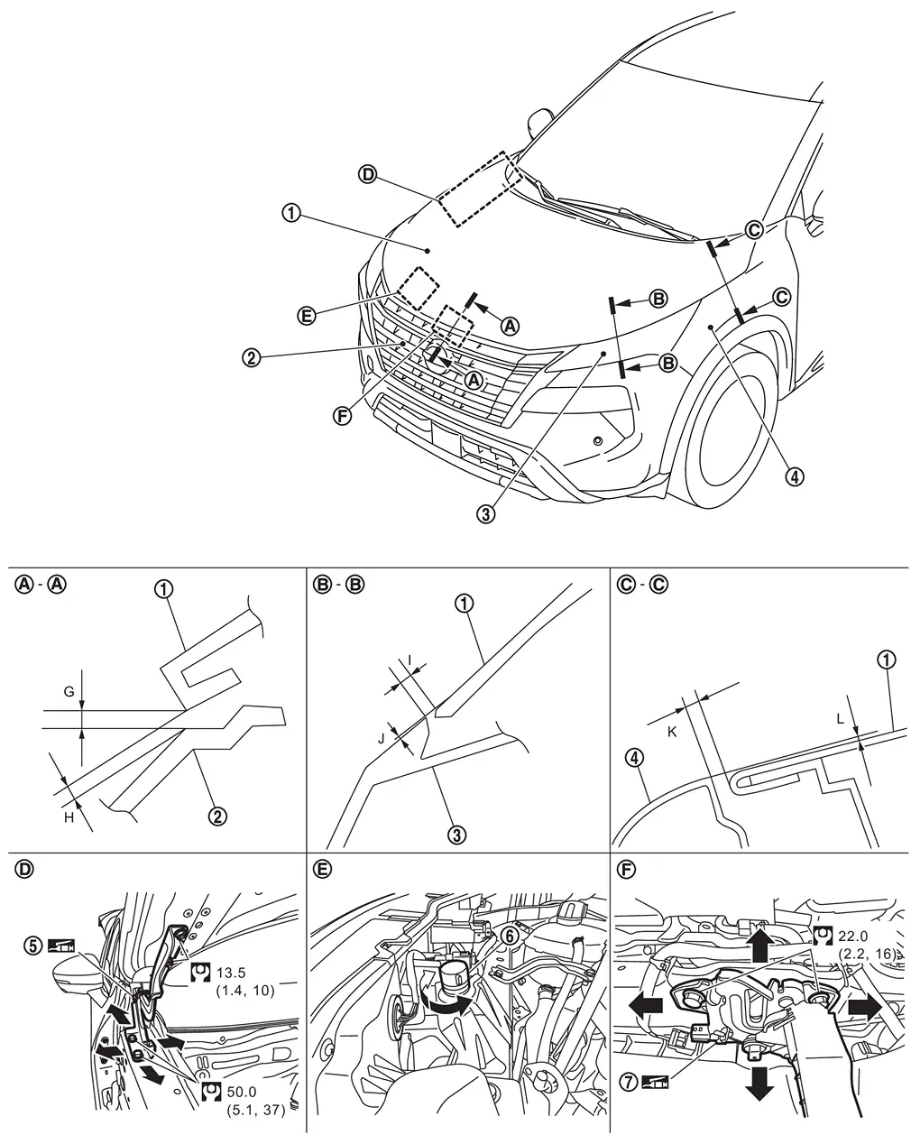
| 1. | Hood assembly | 2. | Front grille | 3. | Front combination lamp |
| 4. | Front fender assembly | 5. | Hood hinge | 6. | Hood bumper rubber |
| 7. | Hood lock assembly | ŌĆö | ŌĆö | ŌĆö | ŌĆö |
 |
: N┬Ęm (kg-m, ft-lb) | ||||
|
: Body grease | ||||
Check the clearance and the surface height between hood assembly and each part by visually and touching.
If the clearance and the surface height are out of specification, adjust them according to the procedures shown below.
Unit: mm [in]
| Portion | Standard |
Difference (RH/LH, MAX) | |||
|---|---|---|---|---|---|
| Hood assembly ŌĆō Front grille |  ŌĆō ŌĆō |
G | Clearance |
2.0 ŌĆō 6.0 [0.079 ŌĆō 0.236] |
< 3.0 [0.118] |
| H | Surface height |
(ŌłÆ1.6) ŌĆō (+2.6) [(ŌłÆ0.063) ŌĆō (+0.102)] |
< 2.0 [0.079] | ||
| Hood assembly ŌĆō Front combination lamp |  ŌĆō ŌĆō |
I | Clearance |
1.5 ŌĆō 6.5 [0.059 ŌĆō 0.256] |
< 3.0 [0.118] |
| J | Surface height |
(ŌłÆ2.3) ŌĆō (+2.3) [(ŌłÆ0.091) ŌĆō (+0.091)] |
< 2.0 [0.079] | ||
| Hood assembly ŌĆō Front fender assembly |  ŌĆō ŌĆō |
K | Clearance |
3.0 ŌĆō 5.0 [0.118 ŌĆō 0.197] |
< 1.5 [0.059] |
| L | Surface height |
(ŌłÆ1.0) ŌĆō (+1.0) [(ŌłÆ0.039) ŌĆō (+0.039)] |
< 1.5 [0.059] | ||
Fitting Adjustment Procedure
Remove front grille cover. Refer to Removal and Installation.
Remove hood lock assembly mounting bolts, and then remove hood lock assembly. Refer to Removal and Installation.
Adjust the surface height of hood assembly according to the fitting adjustment standard dimension by rotating hood bumper rubber.
Remove front fender assembly. Refer to Removal and Installation.
Loosen hood hinge mounting bolts.
Temporary install front fender assembly, front combination lamp and front bumper fascia, and then adjustment clearance of hood assembly according to the specified value by moving hood assembly.
Remove temporary installed parts, and then tighten hood hinge mounting bolts to the specified torque.
CAUTION:
After tightening, apply touch-up paint (the body color) if the paint around hinge and mounting bolts are peeled off during adjustment.
Install front fender assembly. Refer to Removal and Installation.
Install front combination lamp. Refer to Removal and Installation.
Install front bumper fascia. Refer to Removal and Installation.
Install hood lock assembly and temporary tighten hood lock assembly mounting bolts, and then position hood lock assembly and engage hood striker. Check hood lock assembly and hood striker for looseness.
Move hood lock assembly laterally until the center of striker and hood lock assembly are vertical when viewed from the front.
Tighten hood lock assembly mounting bolts to the specified torque.
Install front grille cover. Refer to Removal and Installation.
After adjusting, check the open/close operation. Refer to Inspection.
Hood Hinge
Removal and Installation
REMOVAL
Remove hood assembly. Refer to Removal and Installation.
Remove front fender assembly. Refer to Removal and Installation.
Remove hood hinge mounting bolts, and then remove hood hinge.
INSTALLATION
Note the following items, and then install in the reverse order of removal.
CAUTION:
-
Before installation, apply anticorrosive agent onto mounting surface.
-
Before installation, check the hood hinge rotating part for poor lubrication. Refer to Inspection.
-
After installation, perform the fitting adjustment. Refer to Adjustment.
-
After installation, apply touch-up paint (the body color) if the paint around hinge is peeled off during removal.
-
After installation, check the open/close operation. Refer to Inspection.
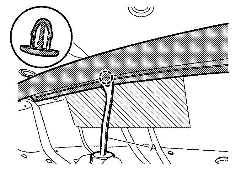
Hood Support Rod
Removal and Installation
CAUTION:
Support hood with a proper material and use protective tape or shop cloth to protect hood and body from falling and damage when removing and installing hood support rod.
REMOVAL
Support hood assembly with a suitable material to prevent it from falling.
WARNING:
Injury may occur if hood assembly is not supported with a proper material when removing hood assembly.
Remove hood support rod from hood support rod grommet.
Disengage hood support rod grommet fixing pawls, and then remove hood support rod grommet from radiator core support.
INSTALLATION
Installation is in the reverse order of removal.
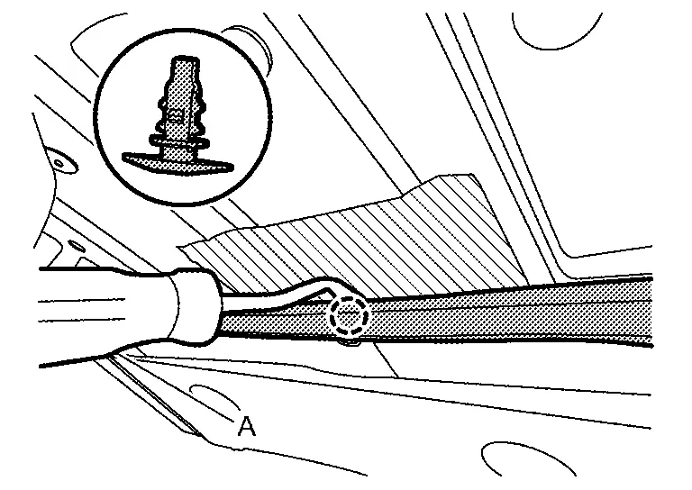
Hood Seal
Removal and Installation
REMOVAL
Apply protective tape (A) on the part to protect it from damage.
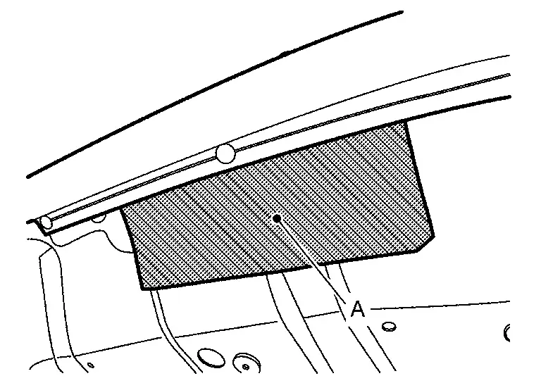
Disengage fixing clips on the reverse side of hood seal using a removal tool (A).
|
: Clip |
Remove hood seal from hood assembly.
INSTALLATION
Installation is in the reverse order of removal.
Radiator Core Seal
Removal and Installation
REMOVAL
Apply protective tape (A) on the part to protect it from damage.
Disengage fixing clips on the reverse side of radiator core seal using a removal tool (A).
|
: Clip |
Remove radiator core seal from hood assembly.
INSTALLATION
Installation is in the reverse order of removal.
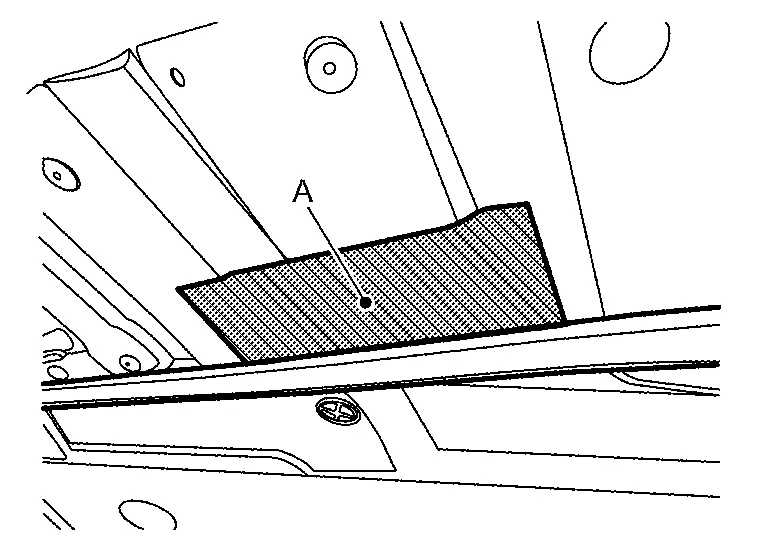
Hood Insulator
Removal and Installation
REMOVAL
Remove hood insulator fixing clips, and then remove hood insulator from hood assembly.
INSTALLATION
Installation is in the reverse order of removal.
Other materials:
Symptom Diagnosis. Low Tire Pressure Warning Lamp Blinks
Description
When the ignition switch is placed ON, the low tire pressure warning
lamp blinks. And then 1 minute later, low tire pressure warning lamp
turns ON.
Diagnosis Procedure
CHECK TIRE PRESSURE SENSOR INSTALLATION
Check visually that tire pressure sensors are installed to each wheels c ...
P2122 App Sensor
DTC Description
DTC DETECTION LOGIC DTC
CONSULT screen terms
(Trouble diagnosis content)
DTC detection condition
P2122
00
APP SEN 1/CIRC
(Throttle/Pedal position sensor/switch D circuit low)
Diagnosis condition
Engine running at idle
Signal (terminal)
Accelerator ...
B120e-55 Ipdm E/r
DTC Description
DTC DETECTION LOGIC DTC No.
CONSULT screen items
(Trouble diagnosis content) DTC detection condition
B120E-55
IPDM E/R
(Intelligent power distribution module engine room)
[NOT CONFIGURED]
Diagnosis condition
When ignition switch is ON
Signal (terminal)
Ō ...