Nissan Rogue (T33) 2021-Present Service Manual: Removal and Installation :: Radiator Core Support
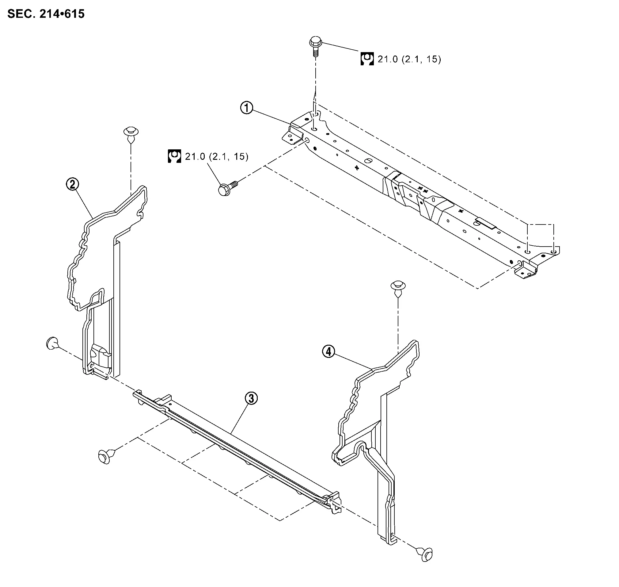
Exploded View
 |
Radiator core support |  |
Radiator air guide RH |  |
Radiator air guide lower |
 |
Radiator air guide LH | ||||
 |
: N┬Ęm (kg-m, ft-lb) | ||||
Radiator Core Support
Removal and Installation
REMOVAL
Remove front bumper fascia. Refer to Removal and Installation.
Remove front combination lamp. Refer to Removal and Installation.
Remove radiator air guide LH and RH. Refer to Removal and Installation.
Remove hood lock assembly. Refer to Removal and Installation.
Remove crash zone sensor. Refer to Removal and Installation.
Remove air duct (inlet). Refer to Removal and Installation.
Remove air duct body mounting bolt. Refer to Exploded View.
Remove hood lock control cable assembly fixing clips from radiator core support.
Remove washer tank inlet fixing clip.
Remove mounting bracket. Refer to Exploded View.
Disengage harness fixing clips from radiator core support.
Remove radiator core support mounting bolts, and then remove radiator core support.
Installation
Installation is in the reverse order of removal.
Radiator Air Guide
Removal and Installation
Removal
Remove front bumper fascia. Refer to Removal and Installation.
Remove radiator air guide RH fixing clips, and then remove radiator air guide RH.
Remove radiator air guide LH fixing clips, and then remove radiator air guide LH.
Remove radiator air guide lower fixing clips.
Disengage harness fixing clips from radiator air guide lower, and then remove radiator air guide lower.
Installation
Installation is in the reverse order of removal.
Other materials:
Type a. Preparation. Preparation
Preparation
Commercial Service Tools
Tool name Description
Variable resistor
Check fuel gauge indication position
Power tool
Loosening screws
...
Dtc/circuit Diagnosis. Combination Switch Output Circuit
Diagnosis Procedure
CHECK OUTPUT CIRCUIT
Ignition switch ON.
Turn ON any switch in the system that is malfunctioning.
Check duty ratios between BCM harness connector and ground by using an oscilloscope.
With type A meter System + ŌłÆ
Voltage
(Approx.)
BCM
Connector Termi ...
Basic Inspection. Intelligent Key Interlock Storing
Description
Always perform the Intelligent Key interlock function storage when
the driver seat control unit is replaced. The Intelligent Key interlock
function will not operate normally if no memory storage is performed.
For details, refer to Work Procedure.
Work Procedure
Intelligent Key I ...