Nissan Rogue (T33) 2021-Present Service Manual: Crankcase Ventilation Valve
Diagnosis Procedure
CHECK CRANKCASE VENTILATION VALVE POWER SUPPLY CIRCUIT
-
Turn ignition switch OFF.
-
Disconnect IPDM E/R harness connector.
-
Check the continuity between crankcase ventilation valve harness connector and IPDM E/R harness connector.
Crankcase ventilation valve IPDM E/R Continuity Connector Terminal Connector Terminal F130 1 E35 66 Existed -
Also check harness for short to ground.
Is the inspection result normal?
YES>>GO TO 2.
NO>>Repair or replace error-detected parts.
CHECK CRANKCASE VENTILATION VALVE INPUT SIGNAL CIRCUIT
-
Turn ignition switch OFF.
-
Disconnect ECM harness connector.
-
Check the continuity between crankcase ventilation valve harness connector and ECM harness connector.
Crankcase ventilation valve ECM Continuity Connector Terminal Connector Terminal F130 1 F72 10 Existed -
Also check harness for short to ground and to power.
Is the inspection result normal?
YES>>GO TO 3.
NO>>Repair or replace error-detected parts.
CHECK CRANKCASE VENTILATION VALVE
Check the crankcase ventilation valve. Refer to Component Inspection.
Is the inspection result normal?
YES>>INSPECTION END
NO>>Replace crankcase ventilation valve. Refer to Exploded View.
Component Inspection
CHECK CRANKCASE VENTILATION VALVE
-
Turn ignition switch OFF.
-
Disconnect crankcase ventilation valve harness connector.
-
Disconnect Fresh air hose and air duct connected to crankcase ventilation valve.
-
Remove resonator. Refer to Exploded View.
-
Check air passage continuity of crankcase ventilation valve as per the following conditions.
 Crankekase ventilation valve
 Resonator
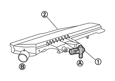
Condition Air passage continuity between  and
and 
12 V direct current supply between terminals 1 and 2 Not existed No supply Existed
Is the inspection result normal?
YES>>INSPECTION END
NO>>Replace crankcase ventilation valve. Refer to Exploded View.
Other materials:
Can Gateway. Precaution. Precautions
Precautions
PRECAUTIONS FOR SUPPLEMENTAL RESTRAINT SYSTEM (SRS) AIR BAG AND SEAT BELT PRE-TENSIONER
: Precautions
The Supplemental Restraint System such as “AIR BAG” and “SEAT BELT
PRE-TENSIONER”, used along with a front seat belt, helps to reduce the
risk or severit ...
Comment activer/désactiver la fonction de maintien de frein automatique
Comment activer la fonction de maintien de frein automatique
1. Lorsque le contact d’allumage du Nissan Rogue est placé sur la position ON, appuyez sur la commande de maintien de frein automatique 1. Le témoin lumineux de la commande de maintien de frein automatique 2 s’allume pour co ...
Diagnosis System (hvac)
CONSULT Function
CONSULT performs the following functions via CAN communication with A/C amp. Diagnosis mode Function
Self diagnosis result
Display non-network DTC which A/C amp. memorizes
ECU identification
The A/C amp. part number is displayed
Active Test
The signals used t ...