Nissan Rogue (T33) 2021-Present Service Manual: Component Parts
Propilot Assist 2.1
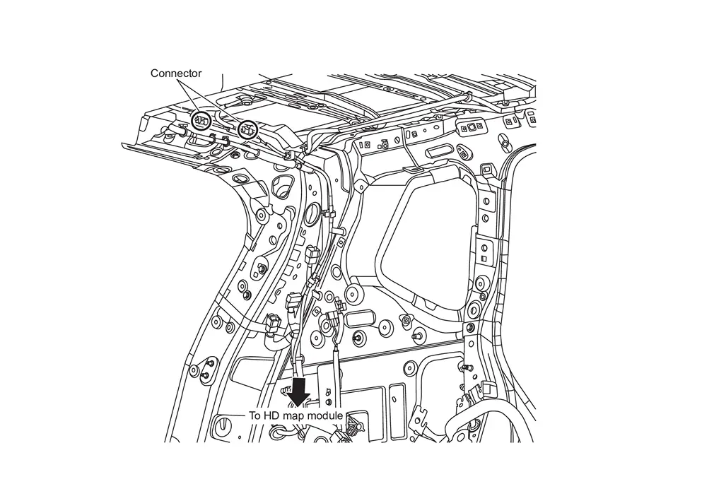
Component Parts Location

| A. | Behind front bumper fascia |
| No. | Component | Function |
|---|---|---|
| 1. | HD map antenna | Refer to HD MAP MODULE. |
| 2. | Side radar rear RH | Refer toComponent Parts Location for detailed component location. |
| 3. | Power network separate relay | Refer to POWER NETWORK SEPARATE RELAY. |
| 4. | Driver assistance camera | Refer to Driver Assistance Camera. |
| 5. | Heater | Refer to Front Camera Unit. |
| 6. | TCU (Telematics Communications Unit) | Refer to Component Parts Location for detailed component location. |
| 7. | ABS (Anti-lock Braking System) actuator and electric unit (control unit) | Refer to Component Parts Location for detailed component location. |
| 8. | Side radar front RH | Refer to Component Parts Location for detailed component location. |
| 9. | Distance sensor | Refer to Component Parts Location for detailed component location. |
| 10. | TCM (Transmission Control Module) | Refer to Component Parts Location for detailed component location. |
| 11. | Side radar front LH | Refer to Component Parts Location for detailed component location. |
| 12. | Power steering control module | Refer to Component Parts Location for detailed component location. |
| 13. | ECM (Engine Control Module) | Refer to Component Parts Location for detailed component location. |
| 14. | IPDM E/R (Intelligent Power Distribution Module Engine Room) | Refer to Component Parts Location for detailed component location. |
| 15. | Electrically-Driven Intelligent Brake Unit | Refer to Component Parts Location for detailed component location. |
| 16. | 8CH CAN gateway | Refer to Component Parts Location for detailed component location. |
| 17. | 12V Sub battery (lithium ion battery) | Refer to Component Parts Location for detailed component location. |
| 18. | ADAS (Advanced Driver Assistance System) control unit 2 | Refer to Component Parts Location for detailed component location. |
| 19. | Front camera unit | Refer to Component Parts Location for detailed component location. |
| 20. | HD map module | Refer to HD MAP MODULE. |
| 21. | Side radar rear LH | Refer to Component Parts Location for detailed component location. |
| 22. | Sonar control unit | Refer to Component Parts Location for detailed component location. |
| 23. | Head Up Display unit | Refer to Component Parts Location for detailed component location. |
| 24. | Driver monitor camera control unit | Refer to Component Parts Location for detailed component location. |
| 25. | BCM (Body Control Module) | Refer to Component Parts Location for detailed component location. |
| 26. | Chassis control module | Refer to Component Parts Location for detailed component location. |
| 27. | Steering assist switch | Refer to Steering Assist Switch. |
| 28. | Combination meter | Refer to Component Parts Location for detailed component location. |
| 29. | Driver monitor camera |
Refer to Driver Monitor Camera. Refer to Component Parts Location for detailed component location. |
| 30. | Steering angle sensor | Refer to Component Parts Location for detailed component location. |
| 31. | ProPILOT Assist 2.1 steering switch | Refer to ProPILOT Assist 2.1 Steering Switch. |
| 32. | Around view monitor control unit | Refer to Component Parts Location for detailed component location. |
| 33. | AV control unit | Refer to Component Parts Location for detailed component location. |
| 34. | Shift actuator relay and stop lamp relay (stop lamp relay) |
|
HD MAP MODULE
FUNCTIONS WITHIN THE SYSTEM
HD map module transmits HD map data to ADAS control unit 2 via Ethernet communication.
INDIVIDUAL FUNCTIONS WITHIN THE SYSTEM
-
HD map module stores HD map data.
-
HD map data cannot be displayed on the screen of navigation system or visually viewed in any other way because HD map data is used to control ProPILOT Assist 2.1.
 NOTE:
NOTE:
The data for navigation system is stored in the AV control unit.
-
If there is the latest HD map data, it is updated automatically. For updating HD map data, refer toSystem Description.
INDIVIDUAL OPERATION
ProPILOT Assist 2.1: Refer to System Description.
PARTS LOCATION
Refer to Component Parts Location.
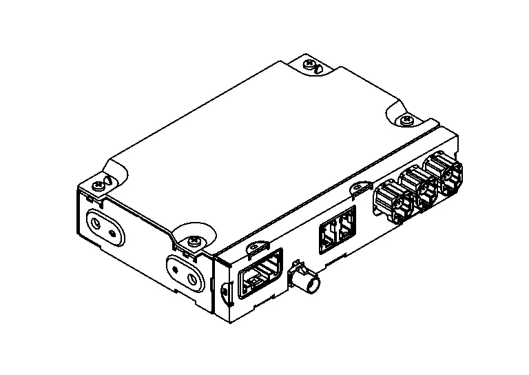
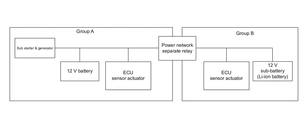
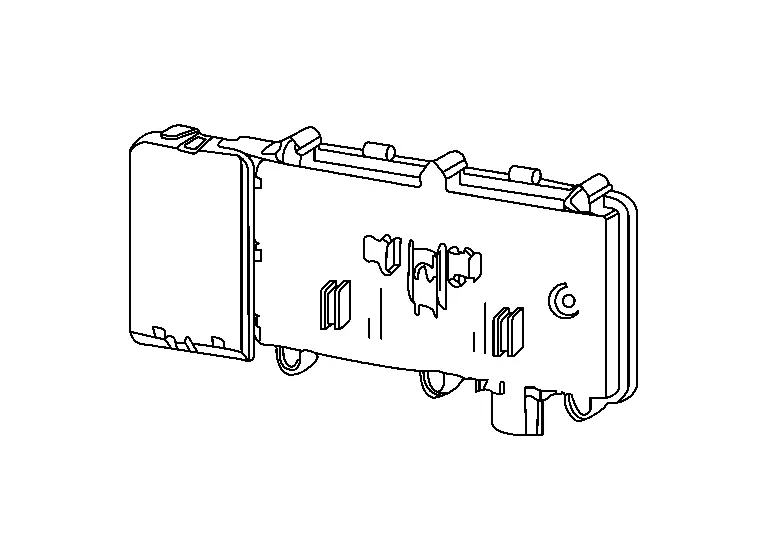
POWER NETWORK SEPARATE RELAY
FUNCTIONS WITHIN THE SYSTEM
-
In order to continue the function of ProPILOT Assist 2.1 even in the abnormal condition, the power supply system of ProPILOT Assist 2.1 is divided into two power supply groups such as sub starter & generator side (Group A) and 12 V sub-battery (Li-ion battery) side (Group B).
-
Power network separate relay is installed between two power supply groups.
-
Power network separate relay detects voltage fluctuation of each power supply group during ProPILOT Assist 2.1 operation.
-
When abnormality occurs on one of two power supply groups during ProPILOT Assist 2.1 operation, power network separate relay cuts off the circuit to maintain function by the normal power supply group.
INDIVIDUAL FUNCTIONS WITHIN THE SYSTEM
Power network separate relay cuts off the circuit between sub starter & generator side (group A) and 12 V sub-battery (Li-ion battery) side (group B) according to voltage fluctuation.
INDIVIDUAL OPERATION
System backup function: Refer to System Description.
PARTS LOCATION
Refer to Component Parts Location.
ROOF ANTENNA AND ANTENNA FEEDER
FUNCTIONS WITHIN THE SYSTEM
-
Roof antenna (GNSS antenna) that is communication antenna of HD map module receives radio waves from global navigation satellite.
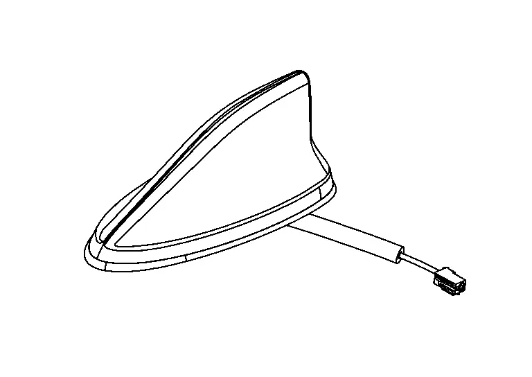
-
Radio wave that received from global navigation satellite is amplified and transmitted to HD map module as GNSS antenna signal.
INDIVIDUAL FUNCTIONS WITHIN THE SYSTEM
Built-in GNSS antenna is used in HD map module.
INDIVIDUAL OPERATION
GNSS antenna is supplied power from HD map module and receives positioning information from global navigation satellite.
PARTS LOCATION
Refer to Component Parts Location.
ANTENNA FEEDER
STEERING WHEEL TOUCH SENSOR
FUNCTIONS WITHIN THE SYSTEM
The steering wheel touch sensor detects driver's steering wheel holding status and transfer its signal to ADAS control unit 2 via LIN communication.
INDIVIDUAL FUNCTIONS WITHIN THE SYSTEM
The steering wheel touch sensor judges if the steering wheel is held or not.
INDIVIDUAL OPERATION
The steering wheel touch sensor is integrated with the entire steering wheel and utilizes electrostatic
capacity change between the electrode of sensor and the hand to judge
whether the steering wheel is held or not.
is integrated with the entire steering wheel and utilizes electrostatic
capacity change between the electrode of sensor and the hand to judge
whether the steering wheel is held or not.
PARTS LOCATION
Refer to Component Parts Location.
ProPILOT Assist Steering Switch
FUNCTIONS WITHIN THE SYSTEM
-
By operating the switch located on the steering wheel, it is easy to operate ON/OFF of ProPILOT Assist 2.1 and set Nissan Ariya vehicle speed/vehicle-to-vehicle distance.
-
The steering switch operation by the driver is input to ECM and transmitted to ADAS control unit 2 via CAN communication.
INDIVIDUAL FUNCTIONS WITHIN THE SYSTEM
-
The steering switch operation by the driver is detected.
INDIVIDUAL OPERATION
-
ProPILOT Assist steering switch consists of a capacitive switch and a combination of resistors.
-
When each switch is pressed, the voltage changes according to the resistance value specified to each switch. ECM reads which switch is operated depending on the voltage.
PARTS LOCATION
Refer to Component Parts Location.
Steering Assist Switch
FUNCTIONS WITHIN THE SYSTEM
Transmits a steering assist switch signal to ADAS control unit 2.
INDIVIDUAL FUNCTIONS WITHIN THE SYSTEM
Steering assist switch allows the ON/OFF of steering assistance function.
INDIVIDUAL OPERATION
Steering assist switch changes the switch operation of driver to the voltage change (ON: 0V / OFF: 12V).
PARTS LOCATION
Refer to Component Parts Location.
Other materials:
Plug
Description
Replace the O-ring if oil leaks from the plug.
Exploded View
1.
Plug
2.
O-ring
3.
Plug
4.
O-ring
5.
O-ring
6.
Overflow plug
7.
O-ring
8.
Transaxle assembly
: N·m (kg-m, ft-lb) : N·m (kg-m, in-lb) : Always replace ...
System
I-Fcw
System Description
SYSTEM DIAGRAM Component Description
ABS actuator and electric unit (control unit)
ABS Actuator and Electric Unit (Control Unit)
Combination meter (FULL TFT METER)
Combination Meter
Combination meter (7 INCH INFORMATION DISPLAY)
Combination Meter
...
Removal and Installation. Intelligent Key Unit
Removal and Installation
REMOVALCAUTION:
When replacing the Intelligent Key unit, always replace it
with a new one. The functions controlled by the Intelligent Key unit
does not operate properly in case of reuse of the Intelligent Key unit
from another Nissan Ariya vehicle.
Remove the instr ...